SRJLH
Hi Kenpeter !
Did You build your SRJLH? And if yes, how did it work out? and how does it sound? I once build an outputstage like yours, but had the upper transistor working as a slave ( SR, Aleph or what you like - I called mine "Alfie". ) It worked fine. I love sound of the JLH, so I`m very interested in your findings.
Thorsten
Last edited:
This is my version with TIP3055 and TIP4XA JLH design I stumbled at Torben's Hi-Fi side emne: Teori while sauntering through web.
Argo
An externally hosted image should be here but it was not working when we last tested it.
Amplificador KB90 – 90 Watts R2 Network
and really works... with 16+0+16V and 3A trafo!
Hi Xandaobh84,
This is a mosfet "upgrade" of a design originally published in HiFi News/Record Review in the mid '70's. The earlier version had Darlingtons. (MJ2500/3001)
I think there is one very minor typo' in the schematic. The P and N channel mosfets have differing input capacitance. Some designers added small caps to one of the devices while I think JLH had one of the resistors increased from 330R to about 1,200R. Don't quote me on this point as I am doing this from memory......
Just moved house and have no idea where my JLH files are at the moment....
Cheers, Jonathan
I posted it here in a new thread :
All FET JLH Class A
Hey Patrick,
Have looked into this before and going without output cap feels a little risky.
But if one added a simple servo from the output to steer the CCS of the input FET we might be safe. Have done a few simple sims and it should work.
Have you consider siomething alittle more hefty as driver? I have tried with IRF510 and 610 models and they seem to work well.
Are you claiming 90W maximum output when powered by a 96VA transformer?
Further, are you claiming 90W maximum output when the maximum AC output voltage cannot exceed 11Vpk to 13Vpk?
So... I start my reply with apologies about my english... is terrible! i'm brazilian....
reply:
with 16+0+16V with 3A you have max 45W (50)
with 30+0+30V with 3A you have max 85W (90)
This original circuit (based on 2N404...) is developed by IBRAPE, in 70's and "sold" in Kits, in Brazil old receivers from CCE, Gradiente, Royal and Magnavox are mounted with this Ibrape Kits.
Hi Xandaobh84,
This is a mosfet "upgrade" of a design originally published in HiFi News/Record Review in the mid '70's. The earlier version had Darlingtons. (MJ2500/3001)
I think there is one very minor typo' in the schematic. The P and N channel mosfets have differing input capacitance. Some designers added small caps to one of the devices while I think JLH had one of the resistors increased from 330R to about 1,200R. Don't quote me on this point as I am doing this from memory......
Just moved house and have no idea where my JLH files are at the moment....
Cheers, Jonathan
Thanks... i'm working in 2 projects FETS based on IRF610... in a few days i show the results... but... i don't like FETS... "they have feelings and they hate me!".. rsrsrs
I have 2 thousands of "toasted" FETs here!
Hi Kenpeter !
Did You build your SRJLH? And if yes, how did it work out? and how does it sound? I once build an outputstage like yours, but had the upper transistor working as a slave ( SR, Aleph or what you like - I called mine "Alfie". ) It worked fine. I love sound of the JLH, so I`m very interested in your findings.
Thorsten
SR vs SRJLH, all else equal? The current steering phase
splitter is redundant, shunts like Aleph don't need JLH.
But divides to conquer the tasks of in-phase splitting,
and quadrature phase shifted current regulation. Does
this separation of tasks matter? I don't know... They
both have to get mixed at the output stage anyway...
It was more an effort to illustrate the simplest possible
quadrature feedback, grafted to the simplest possible
amplifier that could benefit. For purpose of discussion
of such feedback, and how it can shape other classes
besides just Class A. If you are going to use the shunt
to shape other classes, then separating shunt regulation
from phase splitting is an almost mandatory prerequisite.
Its all still a sim and a box of parts that never gets built.
Might be the greatest thing ever, might be a complete
waste of time... No, it probably *IS* the greatest thing.
Just don't count on me to be the first to build it.
When I get home from work, the last thing I want to do
is screw with another damn amplifier.... Granted, I don't
get to design or build them at work. I merely set up test
fixtures for other people's designs I could care less about,
less than half of them having anything to do with audio.
And I also troubleshoot and repair the stubborn ones that
won't cooperate. As the most senior tech, I get the hardest
troubles. After the other techs have given up, and probably
added other damage, and the board is about to go to scrap.
This is where fatigue that spoils all the fun really occurs.
Last edited:
Just out of interest, Jlh proposes in one of his book a simple tweak that could be made to the vas phase splitter transistors. Use of a CFP, anyone tried to see what effect this brings about. Looking at the circuit It seems to me that a high Beta transistor here would also improve performance if cob and early voltage werent affected much.
useless specification!reply:
with 16+0+16V with 3A you have max 45W (50)
with 30+0+30V with 3A you have max 85W (90)
useless specification!
ok! useless for you!
because really works... so sorry!
The best place to look is here:
The Class-A Amplifier Site
and in particular this page:
The Class-A Amplifier Site - JLH Class-A Update
"Fig 3 – The Higher Power Circuit" is what I built.
The Class-A Amplifier Site
and in particular this page:
The Class-A Amplifier Site - JLH Class-A Update
"Fig 3 – The Higher Power Circuit" is what I built.
Hi, Paulb
I am planning to build the high power version of JLH soon (just got my boards from Skycoral) using 2SC5200. I am trying to estimate how big a heat sink should one use (as a start, I plan to set the rail voltage at ~28V and Iq at ~ 2 amp). By the way, what kind of size of the heat sinks are you using? Thanks!
I am planning to build the high power version of JLH soon (just got my boards from Skycoral) using 2SC5200. I am trying to estimate how big a heat sink should one use (as a start, I plan to set the rail voltage at ~28V and Iq at ~ 2 amp). By the way, what kind of size of the heat sinks are you using? Thanks!
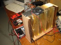
Here's a look of the heatsinks I used. I ended up using fans to use them oriented horizontally, they should be vertical (as shown in the picture) for best performance.
Basically, use the biggest heatsinks you can get. And they'll probably still be too small.
Basically, use the biggest heatsinks you can get. And they'll probably still be too small.
Attachments
with all that woodwork (insulation) around the sinks you are reducing the heat dissipation capability of your sinks.
Is that fan blowing or sucking?
It should be blowing and it should be mounted at the bottom.
You would do better building a card, or plastic, or metal tunnel to divert the fan flow through the sinks.
Is that fan blowing or sucking?
It should be blowing and it should be mounted at the bottom.
You would do better building a card, or plastic, or metal tunnel to divert the fan flow through the sinks.
Here's a look of the heatsinks I used. I ended up using fans to use them oriented horizontally, they should be vertical (as shown in the picture) for best performance.
Basically, use the biggest heatsinks you can get. And they'll probably still be too small.
Hi, Paulb,
Interesting. Are you putting all 8 output BJT's on that heat sink or just 4 (one channel)? I was also thinking using force convection since it is easier to get "narrower" heat sink in whatever length one wants. Place them horizontally face to face and then block the top and bottom to form a tunnel. Place a 120mm or 150 mm fan blowing from one end. Some of these fans can operate very quietly. I suspect this set up should work OK without the resort to huge heta sinks. However, such a design renders the whole amp "packaging" kind of awkward since the left and right channle are now physical divided by the tunnel. I have to build them in dual mono configuration which will jack up the cost.
Thanks for sharing your design.
Andrew,
I'm aware of how to get the most dissipation out of heatsinks, thanks. I'm hoping to do without a fan at all. In the orientation as shown, I didn't need a fan. My prototype as shown ended up using three of them because the box had to fit into a shelf and laid down horizontally.
Lo_Tse,
The three heatsinks were for two channels, 8 transistors. I added a thermal cutout that shut off the power if the heatsink temperature got too high - highly recommended.
Paulb,
Well, my guess from your picture - your heat sink should be around 12" x 10 or 12". Assuming each transistor generates 30-35 watt of heat, you have 8 x 30/35 = 240 to 280 watt to disspiate. Wow, I can see the heatsink would get pretty hot.
Good suggestion! Just curious, what kind of thermal cut out mechanism did you use? By the way, did you use the PCB from Skycoral or you made your own?
Regards
Going from memory (the amp isn't hooked up at the moment) I am running it at about 1.5 amps bias per channel at around 25Vx2, so 75 watts per channel; 150 total. The thermal cutout is a standard device you can get from Digikey or wherever. My power supply was controlled by a relay that was disconnected when the thermal cutout, well, cuts out.
I got my PCBs from Olimex using a design from Geoff Moss (the Class-A amp site guy). I still have the Gerbers etc. if you want:
JLH-2005 – NOTES
If you're still following this thread Geoff thanks once again. Once I find some more space I'll be setting up the amp again. Maybe some repackaging along the lines that Andrew suggested, or fanless.
- Home
- Amplifiers
- Solid State
- JLH 10 Watt class A amplifier