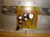
I'm quite happy to announce the birth of my new DAC/miniJLH
Congrats on getting good results, Domingo. How hot does it get there in the summer? You may need to consider drilling even more holes.
When you have a chance, I would try a different input transistor. The KSA992 is very-high hfe and more appropriate for very low-level signals, like from mics, phono carts, tape heads. I'm pretty sure you were driving the 992 into distortion, and probably still are, only less. I would suggest a KSA1015 and put a 2k7 to 3k0 resistor between the input cap and the transistor base to limit the current. And a 68-100pF cap from base to ground to filter RF. Of course, wih a wooden enclusure you might pick up radio stations anyway...
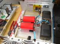
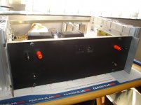
After my initial trials, I have decided to build a full fledged JLH1969.Hello Santiago44, I'm riding my 1969 JLH (10W) - Class A.
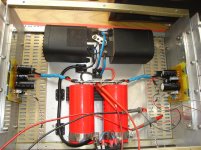
See my power supply and my amplifier circuit.
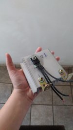
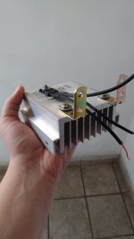
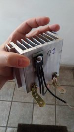
Transistors in the Q1 and Q2 amplifier circuit require large heat sinks.
I noticed that the quiescent current is 1.2A as per the schematic
How big is your heat-sink for one channel?
After my initial trials, I have decided to build a full fledged JLH1969.
I noticed that the quiescent current is 1.2A as per the schematic
How big is your heat-sink for one channel?
Hello Hanair, I used independent heatsinks. 1 for each transistor. Their measurement is: 9.5cm x 11cm x 5cm
If you are putting it in a single heat sink, (Q1 and Q2) you can use it next to: 19cm x 11cm x 5
Tiago Sierra
Attachments
Congrats on getting good results, Domingo. How hot does it get there in the summer? You may need to consider drilling even more holes.
When you have a chance, I would try a different input transistor. The KSA992 is very-high hfe and more appropriate for very low-level signals, like from mics, phono carts, tape heads. I'm pretty sure you were driving the 992 into distortion, and probably still are, only less. I would suggest a KSA1015 and put a 2k7 to 3k0 resistor between the input cap and the transistor base to limit the current. And a 68-100pF cap from base to ground to filter RF. Of course, wih a wooden enclusure you might pick up radio stations anyway...
Dear jbau,
Indeed summer is coming here and it can be quite aggressive in June
")
I might seriously have to drill a new hole every week on it.
For sure I'll try with new PNP transistor. That's a high value advice! The closest I found in stock here is the following. Would you approve it?
https://cdn-reichelt.de/documents/datenblatt/A100/CSA1015-CDIL.PDF
Also the RF filter will be more than welcome. I was picking up some noise from a wireless device yesterday and after panicking a bit (I thought something damaged) I remembered your words. I interpret the 68-100pf cap goes from the PNP transistor base to ground. I suppose also that any value between that range will do the same and have an inaudible effect.
As soon as I do the upgrades I'll come back here again.
Best regards,
Domingo
Congrats on getting good results, Domingo. How hot does it get there in the summer? You may need to consider drilling even more holes.
When you have a chance, I would try a different input transistor. The KSA992 is very-high hfe and more appropriate for very low-level signals, like from mics, phono carts, tape heads. I'm pretty sure you were driving the 992 into distortion, and probably still are, only less. I would suggest a KSA1015 and put a 2k7 to 3k0 resistor between the input cap and the transistor base to limit the current. And a 68-100pF cap from base to ground to filter RF. Of course, wih a wooden enclusure you might pick up radio stations anyway...
Hi Jbau,
could you explain what you mean by "driving the 992 into distortion"? I would have thought that that would be more a function of the circuit design.
Cheers
Mike
Last edited:
could you explain what you mean by "driving the 992 into distortion"? I would have thought that that would be more a function of the circuit design.
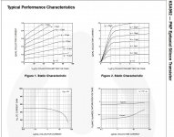
I have been testing PNP's for linearity, and found the 992 to be highly nonlinear with base currents it would encounter as a line-level input device. See attached. It is quite possible I am drawing inappropriate conclusions from this; I am new to the discrete device world.
Last edited:
The first transistor in 1969 operates at a certain collector current <0.1 mA and voltage U / 2. It makes no sense to consider the full range of currents.
DC Current Gain 992 is very linear. https://static.chipdip.ru/lib/776/DOC002776180.pdf
Different types of pnp can be used. In my opinion, a high gain and low noise level in the audio range is required.
DC Current Gain 992 is very linear. https://static.chipdip.ru/lib/776/DOC002776180.pdf
Different types of pnp can be used. In my opinion, a high gain and low noise level in the audio range is required.
Last edited:
In my opinion, a high gain and low noise level in the audio range is required.
So a PNP-JLH with MPSA18?
jbau- your collector current is heading over the limit for the A992. That is rated at 50mA, seems you are hitting that with the first curve. Try much lower base currents.
The 69 JLH input device runs at about 350uA.
The type of transistor used for the input device is unlikely to make a lot of difference to the performance, TBH. The gm of the stage is dominated by the 220 ohm feedback grounding resistor. It won't change much with device, unless you get a particularly poor one which is possible I suppose from a clone manufacturer but shouldn't be from mainstream guys. .
A high gain low noise device is good but I don't think essential as the amplifier is a large signal one. However, if you are going to add resistors to the input as an RF filter that can increase distortion by adding a voltage drop caused by any non-linear base current. In that case a high gain transistor will help keep distortion low.
I've used BC307B, (now BC557B) successfully. But I think a low noise type BC559B or C would be similar to the 2N3906.
DC Current Gain 992 is very linear. https://static.chipdip.ru/lib/776/DOC002776180.pdf
Yes, look at the graph scales. It is very linear with low (single-digit uA or less) base currents, which means either low input levels or very high impedance. Above 1mA collector current, Hfe drops like a rock. (thanks Mark)
Attachments
Last edited:
jbau- your collector current is heading over the limit for the A992. That is rated at 50mA, seems you are hitting that with the first curve. Try much lower base currents.
The 69 JLH input device runs at about 350uA.
My point exactly. 350uA is between the 3rd and 4th sweep line on the tracer!
The type of transistor used for the input device is unlikely to make a lot of difference to the performance, TBH. The gm of the stage is dominated by the 220 ohm feedback grounding resistor. It won't change much with device, unless you get a particularly poor one which is possible I suppose from a clone manufacturer but shouldn't be from mainstream guys. .
A high gain low noise device is good but I don't think essential as the amplifier is a large signal one. However, if you are going to add resistors to the input as an RF filter that can increase distortion by adding a voltage drop caused by any non-linear base current. In that case a high gain transistor will help keep distortion low.
Thx for your thoughts. The input resistor is added to limit the current; the RF filter capacitor was incidental.
I just went through this with the JLH headphone amp, which runs at 100-200uA depending on input levels. The uber-high Hfe devices (KSA992, 2N5087, and others) all imparted their signature and some sounded interesting, even enticing in certain ways. But it became measurably better and audibly much more transparent using a device (KSA1015-Y, Hfe 200-ish) that was linear in the range of use. That is the basis of my recommendation.
Last edited:
I think you mean
Above 1 mA of collector current, hFE drops like a rock. Beta drops like a rock.
Sorry, you're right. Still waiting for tea to brew here, I shouldn't post until it kicks into gear...
Indeed summer is coming here and it can be quite aggressive in June
I might seriously have to drill a new hole every week on it.
Sorry, somehow I missed your post.
For sure I'll try with new PNP transistor. That's a high value advice! The closest I found in stock here is the following. Would you approve it?
https://cdn-reichelt.de/documents/datenblatt/A100/CSA1015-CDIL.PDF
That appears to be their version of the KSA1015 I suggested. I would recommend the -Y version. The -GR starts behaving more like the 992.
Also the RF filter will be more than welcome. I was picking up some noise from a wireless device yesterday and after panicking a bit (I thought something damaged) I remembered your words. I interpret the 68-100pf cap goes from the PNP transistor base to ground. I suppose also that any value between that range will do the same and have an inaudible effect.
That capacitor (which should be NP0 or G0G ceramic, or other low-loss type) works in conjunction with the series resistance preceeding it. The -3dB frequency is 1 / ( 2 * PI * R * C). I tend to choose values in the 300-400kHz range, because AM radio starts in the low 600kHz, and there's a transmitter 1 mile from my house
It is possible to use it in the second stage, but the current gain is normalized above 10 ma - 1 a.
??? Pls explain what you mean by this.
- Home
- Amplifiers
- Solid State
- JLH 10 Watt class A amplifier