Jbau: My Q1 is the same. Limiting current at the base of Q1 sounds interesting, I wonder how different would that be from limiting the input signal directly.
It's a habit of mine for BJT inputs. Limiting input signal level is for output level control. I'd rather have a pot at the amp input than send interpolated data to the DAC...
I consider the input signal as gold that I wouldn't like to trash away into a pot's resistance, to then amplify the signal again. That's why I'm searching for a way to leave the DAC's signal intact and limit the action of the amplifier itself.
Understood. That's why I determined the output voltage needed for my least efficient headphones, configured the amp gain for that, and provide level control for the higher-sensitivity ones.
Is that what the increase of R4 does?Or does R4 decrease gain just because it increases negative feedback?
Gain and amount of feedback are inversely tied together. IMO it's better to leave R5 alone and set the desired gain using R4.
Thank you for your answers. I'll leave gain control in R4 at the moment but it's good to know, if I want a more RAW experience I might rather simply attenuate the input with a pot in the future. I like to see the increase of NFB as 'recycling' the gain surplus for now.
I've learned a bunch thanks to the forum so far and I apologise for my last previous line, certainly not a joke to throw out publicly especially these days.
Regards,
Domingo
I've learned a bunch thanks to the forum so far and I apologise for my last previous line, certainly not a joke to throw out publicly especially these days.
Regards,
Domingo
Oh! I do have a volume pot but in the output. Quite often I mix sound for videos or films and having it in the output gives me a clearer idea of what's happening behind. Also that way I feel more security that I'm not mixing with lowered input levels by mistake.
When mixing the most typical thing to do is equalising, especially using low pass filters, for which zero hiss in the amp is very important. Therefore NFB helps. But too much renders details difficult to distinguish, so the idea of abusing it to reduce gain with R4/R5 is not so good. I'm thinking to include 10K input pots on the boards only to control the fix point of no-distortion, in combination with a small tweak of R4.
When mixing the most typical thing to do is equalising, especially using low pass filters, for which zero hiss in the amp is very important. Therefore NFB helps. But too much renders details difficult to distinguish, so the idea of abusing it to reduce gain with R4/R5 is not so good. I'm thinking to include 10K input pots on the boards only to control the fix point of no-distortion, in combination with a small tweak of R4.
Oh! I do have a volume pot but in the output.
Wait... you have a pot on the output, driving your 60 Ohms-ish headphones?
Oh dear... methinks some of your convictions are leading you astray.
Don't worry they are not convictions, just ideas and some are very bad. Why is it having a direct pot on headphones so bad anyways? Considering that the output has more gain than the input, a pot there should distort less the signal I thought. That was my naive logic at least.
Also, you mentioned adapting voltage of the amp to your headphones. Is that another way to lower gain/distortion? Can you for example modify the input/output voltage ratio (12v/6v in the x-150 board) for that purpose?
Happy workers day and thanks for your patience!
Also, you mentioned adapting voltage of the amp to your headphones. Is that another way to lower gain/distortion? Can you for example modify the input/output voltage ratio (12v/6v in the x-150 board) for that purpose?
Happy workers day and thanks for your patience!
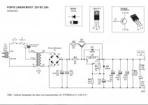
potstip - a couple of points first. I take it this is each supply 24V (i.e. +/-24V) and intended for 4 ohm load?
You will need to be able to measure the current. A voltmeter with a 1V scale would be ideal as you could measure the voltage across one of the load sharing resistors (R13 or R15 for example).
Start with the 50ohm resistor at MAX. (I think the diagram is actually wrong because winding the pot clockwise (I take it upwards towards the + rail) increases the resistance. The wiper should be on the lower end).
VR1 (the 2k pot) should start in the middle.
I suggest this is an iterative process (I have never actually set one of these up!).
Start by setting the output rail to zero using VR1 (with no load). Should not need much trimming from centre, I'm guessing between 25 and 75% of the travel.
Then measure the voltage across one of the load sharing resistors, and slowly wind the 50 ohm pot down in resistance until you measure 185mV across it. That is 1.85A or half the quiescent current needed.
Then check the output centre rail voltage and trim again as the VAS current will cause an imbalance.
Lastly you can check that there is 185mV across all 4 emitter resistors to check uniformity.
I trust you have good heatsinks (45W per transistor will need at least 1C/W per device) and a suitable PSU. This is hot stuff.
I don't think this circuit is actually ideal. The two pots should have limiting resistors. In the case of the 50 ohm I would think 10 ohms suitable, but it maybe that some transistors will need more current, so 4.7 ohms might be needed. That would at least be 10% of the range and provide some degree of protection against inadvertently starting with zero ohms. Same for the 2k pot but here I suggest 470 ohms as a reasonable limiting value.
Hello folks;
As John mentioned "i saw 185mV across the R16 resistor and That is 1.85A or half the quiescent current needed."
Do i need to increase it to 370mV to reach 3.7A Quiescent Current or 185mV means 3.7A already? It is already damn hot
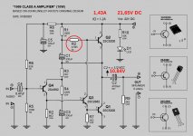
REV. in my JLH 1969 (10W) DC
Hey guys,
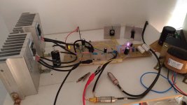
I'm doing the last tests on my JLH 1969 10W (DC) before fixing the components on the board.
I removed the trimpots (KT1 and KT2) and put resistors in place.
My load is 6 ohms (speakers).
The current got high. 1.43A.
I will then increase the resistor R2 (470R).
I want to lower the current so that it is between 1.1A ~ 1.2A
Perhaps a 560R resistor? or 680R? in R2.
Sounds very good!!! Very crystalline
Att. Tiago Sierra.
Hey guys,
I'm doing the last tests on my JLH 1969 10W (DC) before fixing the components on the board.
I removed the trimpots (KT1 and KT2) and put resistors in place.
My load is 6 ohms (speakers).
The current got high. 1.43A.
I will then increase the resistor R2 (470R).
I want to lower the current so that it is between 1.1A ~ 1.2A
Perhaps a 560R resistor? or 680R? in R2.
Sounds very good!!! Very crystalline
Att. Tiago Sierra.
Attachments
Tiago! To reduce the current, increase the resistor R2. Check after heating for 30 minutes.
OK OldDIY, thanks! I will change.
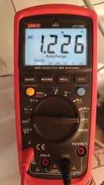
TEST NOW:
R2 = 470R
1h30 amp ON
ambient temepratura = 24ºC
Q2 = 60ºC (heatsink = 42ºC)
Q1 = 51ºC (heatsink = 41ºC)
Tiago! To reduce the current, increase the resistor R2. Check after heating for 30 minutes.
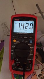
Amp ON (1h 30m)
Current: 1.42A
(still R2 = 470R).
Speaker 6 ohms.
Attachments
Why is it having a direct pot on headphones so bad anyways? Considering that the output has more gain than the input, a pot there should distort less the signal I thought. That was my naive logic at least.
Your headphones have a very nonlinear (uneven) impedance vs frequency. If you put a pot between it and the amp, the resistance of your pot is dividing the voltage against that uneven impedance, making the sound spectrum sound increasingly like the impedance curve. By contrast, the input impedance of the amp is very high, causing no such problem at audio frequencies.
What value (and wattage) of pot are you using?
Also, you mentioned adapting voltage of the amp to your headphones. Is that another way to lower gain/distortion?
As explained before, lowering the gain via the feedback resistors increases the amount of negative feedback which lowers the distortion. They're not separate.
Can you for example modify the input/output voltage ratio (12v/6v in the x-150 board) for that purpose?
I don't understand the question...
I am selling JLH modules if anyone interested.
https://www.diyaudio.com/forums/swap-meet/371748-fs-jlh2003-modules.html#post6639448
https://www.diyaudio.com/forums/swap-meet/371748-fs-jlh2003-modules.html#post6639448
R2 = 560R
Hello oldDIY, I replaced the resistor R2.
I replaced the 470R with a 560R (5W)
IQ = 1.23A
I left the amplifier on for 1 hour.
Thanks for the tip.")
Tiago! To reduce the current, increase the resistor R2. Check after heating for 30 minutes.
Hello oldDIY, I replaced the resistor R2.
I replaced the 470R with a 560R (5W)
IQ = 1.23A
I left the amplifier on for 1 hour.
Thanks for the tip.
My introduction to Class A
Hi guys I`m looking for information to build my first class A, so I saw a lot of this chinese kits of the JLH 1969 and i want to know the limitation of this kits, my plan is to use 2 speakers full range 30w 6oms each, and I do not know which PSU use, and how to scale all mesures, so I whant some recomendations of PSU`S and informations about another projects and how to scale this project
Hi guys I`m looking for information to build my first class A, so I saw a lot of this chinese kits of the JLH 1969 and i want to know the limitation of this kits, my plan is to use 2 speakers full range 30w 6oms each, and I do not know which PSU use, and how to scale all mesures, so I whant some recomendations of PSU`S and informations about another projects and how to scale this project
Audition - My JLH 1969 10W (22V DC)
Hi oldDIY, I put a video here, showing a little bit of the audio quality of my JLH.
Test - AMP JLH 1969 (10W) 22V DC - YouTube
Audio is not very good, as it was recorded with the cell phone mic.
I am finalizing the assembly of the amplifier, to make it stereo.
Getting ready I show his amplifier and sound quality recording with a recorder.
Tiago Sierra
Tiago! To reduce the current, increase the resistor R2. Check after heating for 30 minutes.
Hi oldDIY, I put a video here, showing a little bit of the audio quality of my JLH.
Test - AMP JLH 1969 (10W) 22V DC - YouTube
Audio is not very good, as it was recorded with the cell phone mic.
I am finalizing the assembly of the amplifier, to make it stereo.
Getting ready I show his amplifier and sound quality recording with a recorder.
Tiago Sierra
Attachments
Hi guys I`m looking for information to build my first class A, so I saw a lot of this chinese kits of the JLH 1969 and i want to know the limitation of this kits, my plan is to use 2 speakers full range 30w 6oms each, and I do not know which PSU use, and how to scale all mesures, so I whant some recomendations of PSU`S and informations about another projects and how to scale this project
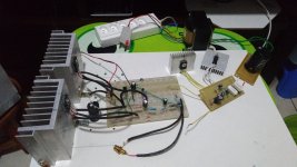
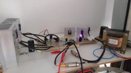
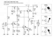
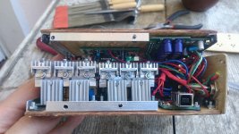
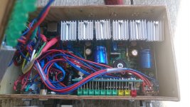
Hello Santiago44, I'm riding my 1969 JLH (10W) - Class A.
See my power supply and my amplifier circuit.
Transistors in the Q1 and Q2 amplifier circuit require large heat sinks.
Attachments
Your headphones have a very nonlinear (uneven) impedance vs frequency. If you put a pot between it and the amp, the resistance of your pot is dividing the voltage against that uneven impedance, making the sound spectrum sound increasingly like the impedance curve. By contrast, the input impedance of the amp is very high, causing no such problem at audio frequencies.
What value (and wattage) of pot are you using?
As explained before, lowering the gain via the feedback resistors increases the amount of negative feedback which lowers the distortion. They're not separate.
I don't understand the question...
Dear Jbau and DIYers,
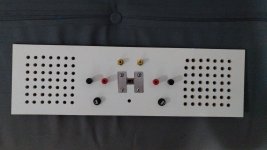
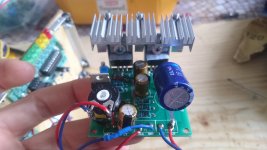
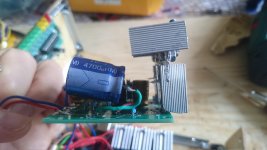
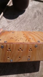
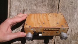
I'm quite happy to announce the birth of my new DAC/miniJLH, call it Gloria. That came to me in a moment were I found the sound to be just glorious
I guess I should had written before, but I was busy taking some definitions, testing and finalising the box. After burning out some resistor, I drilled more holes and now temperature seems mild and stable. Let's hope it lasts. Five heatsinks per board, bias current at 0.13A (+/-12 VDC).
Finally I solved the distortion problem soldering a 10K trimmer (0,25W) to the input of each board, bringing back the NFB resistors to their original values. These trimmers are also quite useful to correct the imbalance of the preceding input stereo pot (50K 0,1W currently, but I reckon that's too high, considering the extra 10K pots in each board). Of course, following @jbau observation and explanation, I removed the volume control after the amp's output. I wish attenuating at that stage would be possible, but frequency fluctuations is the least I want.
I replaced most Elcos with Nichicon gold, sound is much brighter than with the factory Chong-X. For the output cap I used the best I had at hand, an ELNA 4700uF 16V. It sounds correct to me, although the high capacitance compared to the schematic 2200uF might be cutting off low frequencies ?
Also increased the 220R before the VR to 1K, to bring down bias current to the actual point.
In the to-do list is to replace the film plastic input cap to something better. I tried some 2,2uF Nichicon Muse bipolar I had, quite sharp and detailed results but bass was gone. I read good things about Metallic Polypropylene. I might try some Wima MKP that are sold here but not cheap. Would be 1uF appropriate or will I need something higher? I've read people using up to 4,7uF for MKP input caps.
All in all, there are only details to be solved and a lot already learned. I'm quite surprised of the sound quality that ended up in a small box, although it was not my intention to have everything so tight at the beginning. Things just came in and the box remained the same.
All my gratitude to everyone else who helped me with their invaluable thoughts: OldDIY
kozard
kronzilla
fredbloggstwo
Best regards and happy listening!
Domingo
Attachments
Last edited:
- Home
- Amplifiers
- Solid State
- JLH 10 Watt class A amplifier