Member
Joined 2009
Paid Member
Exactly: Grado 60s can be driven off the smell of an oily rag. Stax electrostatics or the big Sennheiser cans need a solid watt per channel.
(Ironically, for such amps you need a "power soak" to drop 20 or 30db if you're going to use the grados with them without running out of volume knob sensitivity. Ask me how I know)
Grado 60’s, I remember those, my god, was like sticking needles in my ears.
Not together, but instead
Replace R4 (220) with another (680 ohm).
You can reduce R5 to 1kΩ (in parallel). Gain decreases, distortion decreases due to the higher NFB.
The signal can also be attenuated with a 10 kΩ pot at the amplifier input.
I replaced R4 for a 680 ohm and I'm in the 7th heaven.
In gratitude to @OldDIY and everyone who took their time to answer let me please share here the music that accompanied me during all these tests. With the JLH and TDA1387 DAC I could easily even hear the pianists' chair (as if I was almost there). I hope you enjoy it and once I assemble everything together I'll post few pictures here.
Hania Rani – Live from Studio S2 - YouTube
Regards
Domingo
Hi Chumingo
With a very simplistic calculation: if your power supply is 12 volts, you will get a peak to peak swing of about 10 Volts before the output transistors saturate and it starts to clip and distort badly.
10 volts pk tp pk is approx (10/2)/1.4 =3.6 volts rms.
Assuming that you headphone impedance is 63 Ohms, to get 3.6 volts rms into 63 ohms, needs about 3.6/63 = 0.057 Amps.
I am not familiar with the headphone amp version, but the JLH usually needs about 0.7 of this as the quiescent current- which is 40mA - so round it up to 50mA.
Assuming that the output is set to be at the mid point of the power supply, (6 Volts) the idling dissipation in each output transistor is going to be about 12/2 Volts x 0.05 Amps =approx 300mW.
I would suggest you at least triple this for heatsink calculation purposes.
Check my maths - did I miss anything guys?
Happy listening
Mike
Dear Mike,
I appreciate back the calculation you shared with me, it makes all sense to me but it leaves me in doubt–because of my ignorance. Should I want to bring down quiescent current to 0.05A? In order to give my headphones what they really need.
I'm asking this because in post #7929 I was suggested by @OldDIY to set it in 0.12-0.15A, which is quite higher.
In any case, the minimum value I get by turning the variable resistor is 0.19A. Is there a way to reduce current further? By replacing the resistor at the driver emitter I'm reducing gain to desirable levels, but quiescent current remains high and therefore the amplifier might be producing more heat than necessary. I'm also afraid that the quality of sound I'm getting, although very pleasant, might be suffering because of current being so high up.
Regards,
Domingo
Hi Domingo,
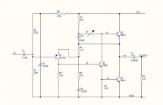
I have found what I think is the schematic of the 3 Watt version from the link on Ebay that you gave. It is the original 1969 circuit and there are several interpretations on exactly how the JLH (1969) circuit works as an AC amplifier.
As OldDIY has said, increasing R6 will decrease the adjustment range of R7, and 1K seems a good value to start with if you want to do that.
With regards to 'Is it a good thing?' to have the Iq as high as 120mA or greater, its down to your ears and the amount of heatsink you can provide without the output transistors getting too hot -(>50 degrees C or so)
Also note that the 63 Ohms value for your headphones is just a nominal value and will vary significantly.
Bottom line: use lots of heatsink, adjust Iq to a value that sounds good to you and don't worry too much about its absolute value.
Hope this helps.
Mike
Grado 60’s, I remember those, my god, was like sticking needles in my ears.
Sorry to hear that: you should have got a refund (I'm assuming you're saying they shrieked i.e. 3khz-7khz resonance). That's the last thing I'd accuse them of being. They're a bit forward but not in-your-face like a bad wizzer.
Cheap yes, nasty no.
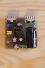
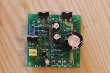
Just for the record, the seller of the mentioned eBay publication (named "tubeshunter") doesn't seem serious enough to me, since the kit in the publication and the diagram (!) don't correspond to what I received from him. The boards in the publication are double layered, whereas the ones I received are single (with quite narrow circuit paths). Besides, the diagram published–original JLH –is for 5 capacitors, whereas the kit received has 7 capacitors. The two extra caps go before the line output, one of them ceramic. I tried to complain but the seller simply insisted this is a JLH
Anyways, maybe those extra caps are the reason why I noticed a big difference of sound between that kit and another mentioned board I got from a Chinese retailer, which sounds much less muffled in my opinion. I analysed and wrote down the circuit of the latter and this time it is exactly the same than the diagram published (but not sent) by the eBay seller.
In attachment you can see both boards, one has more capacitors than the other.
–is for 5 capacitors, whereas the kit received has 7 capacitors. The two extra caps go before the line output, one of them ceramic. I tried to complain but the seller simply insisted this is a JLH Anyways, maybe those extra caps are the reason why I noticed a big difference of sound between that kit and another mentioned board I got from a Chinese retailer, which sounds much less muffled in my opinion. I analysed and wrote down the circuit of the latter and this time it is exactly the same than the diagram published (but not sent) by the eBay seller.
In attachment you can see both boards, one has more capacitors than the other.
Attachments
Last edited:
Domingo: In attachment you can see both boards, one has more capacitors than the other - Do reverse engineering. Draw up a diagram for the PCB. You can find a resistor color coding table on the Internet.
The circuit on the right (1969mini) contains the main part of the 1969 amplifier. Power filter capacitors, LED indicators, etc. may be added to other manufacturers' boards.
The circuit on the right (1969mini) contains the main part of the 1969 amplifier. Power filter capacitors, LED indicators, etc. may be added to other manufacturers' boards.
In attachment you can see both boards, one has more capacitors than the other.
I got a couple of the boards on the right, labeled XR-150, to experiment with as headphone amps. I haven't listened to them, but the distortion measured quite good completely stock. The only caps missing are the power supply input filter caps, which you can easily add yourself. Their value depends on the supply being used.
Member
Joined 2009
Paid Member
Sorry to hear that: you should have got a refund (I'm assuming you're saying they shrieked i.e. 3khz-7khz resonance). That's the last thing I'd accuse them of being. They're a bit forward but not in-your-face like a bad wizzer.
Cheap yes, nasty no.
I sold them on. As the prices in Canada were outrageous at the time I had a friend buy them in the US on a business trip so there was no option to return them. It was my first foray into so-called hi-end wired headphones. I had build a discrete Class A amp for them. The bad experience resulted in me never trying headphones again, that was more than a decade ago.
I just wonder what the bias current is for the one on the left. It might be set for a very low bias current which might explain some of the observations.
The ones I bought look like the right photo.
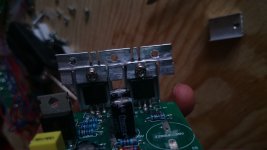
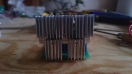
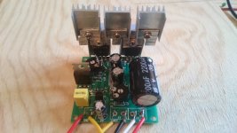
@kronzilla: I added new heatsinks for security, using a piece of aluminium to bring together 5 of those little pieces I had (my space box space is limited). Challenge was to maintain electric isolation but so far it's enough for the bias current range in which I'm testing, between 0.25-0.05A.
I find strange that I cannot hear much audio differences going up and down with current. Even tested at 0.02A and it still sounds stable with my 63ohm headphones. After paying a lot of attention maybe I started feeling blended differences of pitch responsiveness among different power, based on voice and piano listening, so I found a sweet spot in 0.13A at the moment, tuneable with a 10K pot I installed in place of the 220ohm resistor and the 1000-2000k VR that weren't sufficient to go down enough. It runs cold as a cup of tea that you almost don't wanna drink anymore. At 0.25A it gets warm but touchable like a hot water bottle at night
Capacitors are branded Chong-X. Rubycons are a good brand but these Chong sound more detailed and with more dynamic response. I mean this after removing the Chong 2200uF cap from the board and testing a Rubycon in its place (yes, the boards I didn't like getting stripped out). But not sure if I'll get tired of the Chong's aggressiveness and maybe a better test for consistency would be to substitute all caps, which I might do with the other channel's board...
@jbau: Mine is certainly the same board, labeled X-150. But I got a lot of (clipping) distortion out of the box, maybe because my DAC's line level is simply too hot for it ??.
I'm reducing gain using a(nother) 2.5K pot I installed in place of the 220ohm resistor before the feedback capacitor (R4 in the diagram shared here again, R6 in the X-150). As resistance increases gain decreases and around 1.1k distortion dissapears for me. I also tried modifying the 2.7K resistor before the PNP emitter (R5 in the diagram), as resistance lowers gain decreases. Reduction with R5 didn't seem to give results as sharp or solid as reducing R4 though, but this was difficult to compare side by side and I wonder if there should be in theory a difference between both methods of gain control, or rather they both do the same (ie. increase NFB because of voltage division).
Attachments
@chumingo: My apologies, I reduced the gain before testing. With no level control you were no doubt exceeding its limits. I replaced R4 with 1.5k for gain just under 10dB. My dacs output over 2VRMS so that is plenty for my most voltage-hungry headphones. If I decide to use it, it will have a 10k pot on the input, plus some resistance into Q1's base to limit the current with the pot wide-open. Q1 is an unbranded 2SA1015 on mine. I plan on replacing Q2 with something faster and higher Hfe.
I like your custom bracket for the heatsinking. I will be surpriised if it is enough, though.
I like your custom bracket for the heatsinking. I will be surpriised if it is enough, though.
Last edited:
Jbau: My Q1 is the same. Limiting current at the base of Q1 sounds interesting, I wonder how different would that be from limiting the input signal directly.
I consider the input signal as gold that I wouldn't like to trash away into a pot's resistance, to then amplify the signal again. That's why I'm searching for a way to leave the DAC's signal intact and limit the action of the amplifier itself. Is that what the increase of R4 does? Or does R4 decrease gain just because it increases negative feedback?
Do you know the answer to this @OldDIY? I understood from a previous answer of yours that the increment of R5 increases NFB, but what about R4? It does the same? Sorry to insist on this question.
On the heatsink: To avoid short circuit I carefully cut off the head of a plastic spacer and insert the remaining little tube in the hole of the bracket. So each transistor has two plastic spacers, the one visible in the picture and another headless one hiding in the bracket's hole. There are also two insulating micas in each transistor. One mica on the side of the heat sink and another on the bracket side (not visible in the 1st two pics that I took before isolation). Also M3 screws had to be changed for longer ones. The system works but has to be done very carefully especially the placement of the headless bushing in the bracket's hole. Using sticky compound helps and temperature distributes quite nicely all around. But I understand if you think this is meant to We all are ain't we
I consider the input signal as gold that I wouldn't like to trash away into a pot's resistance, to then amplify the signal again. That's why I'm searching for a way to leave the DAC's signal intact and limit the action of the amplifier itself. Is that what the increase of R4 does?
Or does R4 decrease gain just because it increases negative feedback? Do you know the answer to this @OldDIY? I understood from a previous answer of yours that the increment of R5 increases NFB, but what about R4? It does the same? Sorry to insist on this question.
On the heatsink: To avoid short circuit I carefully cut off the head of a plastic spacer and insert the remaining little tube in the hole of the bracket. So each transistor has two plastic spacers, the one visible in the picture and another headless one hiding in the bracket's hole. There are also two insulating micas in each transistor. One mica on the side of the heat sink and another on the bracket side (not visible in the 1st two pics that I took before isolation). Also M3 screws had to be changed for longer ones. The system works but has to be done very carefully especially the placement of the headless bushing in the bracket's hole. Using sticky compound helps and temperature distributes quite nicely all around. But I understand if you think this is meant to
We all are ain't we
Last edited:
- Home
- Amplifiers
- Solid State
- JLH 10 Watt class A amplifier