Member
Joined 2009
Paid Member
Bigun, thank you for showing me you schematic. It is simple and elegant. Maybe I will give it a try in the future. But for the moment, I prefer to stick with the original schematic and the PCBs I have. If I lower R5 to 0 ohms, the gain becomes unity. But what about the amp distortion and stability ? I don't know.
Me too - I don't know either
")
You can a) try it and see if it oscillates - with a load attached; then fix it with some compensation (JLH has some examples of how to add compensation to this amp in his articles) or b) if you are comfortable using SPIC simulation and have good device models then you can check stability in software first.
Me too - I don't know either
You can a) try it and see if it oscillates - with a load attached; then fix it with some compensation (JLH has some examples of how to add compensation to this amp in his articles) or b) if you are comfortable using SPIC simulation and have good device models then you can check stability in software first.
I'm afraid this is probably beyond my current skills. That's why I hoped someone tried this before.
I have no oscilloscope for doing a).
About b) : I don't know what I'm looking for. But if it is just looking for ripples on square waves, then yes I can do it. I searched the acticle where JLH talks about compensation but I couldn't find it.
I've just tried simulating the JLH69 at unity gain and its a mess. Fine on sine testing but squarewaves are a no go even with compensation caps thrown all over the place.
Great! You save me a bunch of time!
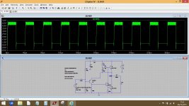
I tried with a 10kHz square wave 4V p-p but I have not seen any problem. At which frequency did you find a issue? You did the test with R5=0 ohms?
Last edited:

Member
Joined 2009
Paid Member
I have found that the transistor models do change the SPICE results - I would imagine that things like the device transconductance and capacitances are relevant but I'm not sure which parameters are modelled by Spice. You do need to look at 'real' loads though, a simple 8R resistor doesn't tell the story of a speaker or a speaker cable. In Spice us add a capacitor in parallel with the 8R 'load' and this always has some impact on stability.
I have had a SS power amp go "rouge" and take out a speaker before.
Due to the fact that this amp has an output capacitor (C2) can this amp
take out a speaker?
Thanks for answer.
i doubt it, amps like this blocks dc that can damage speakers, btw, make sure you have a resistor after C2 the speaker end, caps like that are never left without any terminating resistor...100 ohm to 1k 0hm 2 watts will do fine...
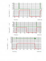
SPICE is reasonably good at modelling transistors, but the parameters have to be accurately derived. Not all SPICE models are as good as the transistors they are supposed to represent. Here are some simulations of the JLH69 amplifier - first using 2N3055 (epi base) transistors, then using MJL3281A transistors.
The top curve shows the base-emitter voltage of the input transistor while the square wave shows the output signal. Note that the 2N3055 has uneven rise/fall times, with the rise time slow. Along with this is the huge reverse emitter-base voltage which illustrates "transient distortion" effects - the transistor will be cut off during this pulse.
With the MJL3281A transistors the rise time is MUCH quicker (and the amp sounds better) but although the simulator seems to think that the amp is stable, in a real circuit I needed a 33pF capacitor across the feedback resistor. With a 330pF capacitor the rise time is still faster than the 2N3055 but the transient overload has almost vanished, although there is some internal ringing indicating that some more optimisation might be required.
So even moderately good epi base transistors are not very good in the JLH69, but new transistor types (emitter island) with high fT's should sound better.
Attachments
A Dear John request?
Yes, please.
I too would like to see comparisons with and without the modified compensations.
I know from some other JLH build guides, that JLH measured to find anomalies that had a sound character and used these measurmeents to optimise the circuit behaviour to make it sound "right".
I think he avoided the term "to make it sound good".
Hi gannaji and Andrew
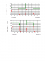
I've used a 2N3716 model for the MJ480 which is the nearest I have (I don't think anyone would have a model for the MJ480 now as it is long obsolete). I did not use the output RC network as the simulator already uses a resistive load (despite JLLH assertion it is not optional!).
The result of this is shown in the attachment. As you can see the rise/fall times are more even, which is a good sign that the compensation components are controlling the behaviour, but the input stage still manages to overload on the rising edge, however. The RC network across the base of Tr3 will tend to cause this.
My preference is this: consider the whole circuit. The compensation method shown in the old Wireless World page was a standard approach, but mainly used for amplifiers with class AB output stages having driver and output transistors. The JLH69 circuit uses a Darlington stage and so why not compensate the output transistor in the compensation loop? This will try to provide the compensation required by the (slower) output transistors. The second simulation pair shows the result of connecting the 1nF compensation capacitor across the feedback resistor R3, without the 100ohm-1nF pair. It has virtually suppressed the transient overload.
In the simulation, the use of a resistive load may give a false sense of security. To try such a configuration in a real circuit may require some additional steps to prevent oscillation. First, the input stage is susceptible to a high impedance causing an undesired phase shift. This is the danger of using high value input resistors. If the preamp is disconnected, the 50k impedance may give rise to oscillation. This can be circumvented by using, say, a 47ohm and 47pF capacitor in series connected between the base of Tr4 and ground. Secondly, any output stage capacitance may cause a phase shift again, and the proverbial RC network as shown may be required along with the usual LR series network too, but the inductor value should not need to be too high (2 to 3 uH I'd guess).
Attachments
Last edited:
SPICE is reasonably good at modelling transistors, but the parameters have to be accurately derived. Not all SPICE models are as good as the transistors they are supposed to represent. Here are some simulations of the JLH69 amplifier - first using 2N3055 (epi base) transistors, then using MJL3281A transistors.
The top curve shows the base-emitter voltage of the input transistor while the square wave shows the output signal. Note that the 2N3055 has uneven rise/fall times, with the rise time slow. Along with this is the huge reverse emitter-base voltage which illustrates "transient distortion" effects - the transistor will be cut off during this pulse.
With the MJL3281A transistors the rise time is MUCH quicker (and the amp sounds better) but although the simulator seems to think that the amp is stable, in a real circuit I needed a 33pF capacitor across the feedback resistor. With a 330pF capacitor the rise time is still faster than the 2N3055 but the transient overload has almost vanished, although there is some internal ringing indicating that some more optimisation might be required.
So even moderately good epi base transistors are not very good in the JLH69, but new transistor types (emitter island) with high fT's should sound better.
You could try converting the lead compensation 330 pf//2k7 to a step network by putting a stopper resistor in series with the 330 pf capacitor.
- Home
- Amplifiers
- Solid State
- JLH 10 Watt class A amplifier