This is worst case. The maximum voltage will be approx. 20V, but on load the voltage will almost certainly be lower. The minimum voltage of the PSU has to be higher than the Vce sat of the pass transistor(s) which may be 3V or higher, but this depends on the value of the smoothing capacitor. I doubt you could have a 3V signal on a pass transistor as the capacitor ripple voltage could be this high, so at a minimum the Vce would vary between 3and 6V. There is no fixed rule, you have to calculate the ripple voltages based on your transformer and rectifier impedances, smoothing capacitor and so on to set the operating limits.
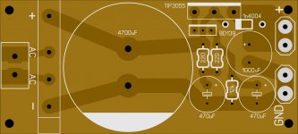
I etched it on a board. I can put two on one board 81mm x 81mm with a scribe down the center so it can be used for two rails. The board would qualify for the prototype discount.
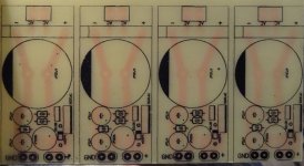
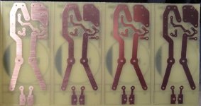
Nice boards, maybe you could upload files/pdf, so we could etch our own boards?
Nice boards, maybe you could upload files/pdf, so we could etch our own boards?
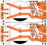
Sure. I worked it over a little to add some more copper and added Fast-on and euro style connectors to both ends of the boards. I also added holes to form a scribe if the boards are bought from a board house so they can be split. This is for iron transfer. Let me know if you need photo etch instead.
Blessings, Terry
Attachments
Hi everybody,
I just finished my JLH1969 clone. This is my first SS class a.
When I power one board with 13VDC it draws .6amps from B+ 21.6 watts.
When I up to 24.0VDC (recommended), it draws 1.45 amps 34.8 watts.
At 13v the heath sink gets warm, at 24v it gets HOT.
How much heath sink area should I be using for 24v?
The kit came with 2SD1047's. All parts and pcb's $18.00 usd shipped.
Thanks
Bruce
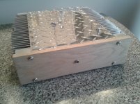
Exemple of heatsink
Hi,
If you can tolerate a max heatsink temp of 50C based on an ambient of 25C, it means a rise of 25C max. So 25C/35W = 0.7C/W heatsink per channel. The one I use are each rated 0.55 C/W which is a smaller number meaning a bigger heatsink, the one shown on the picture are 12 inches deep x 3 inches high and 2 inches wide fines. My bias is at 27V, 1A therefore 27W. Each heatsink are at about 40C once warm.
Hope this helps,
Eric
Attachments
Hi everybody,
I just finished my JLH1969 clone. This is my first SS class a.
When I power one board with 13VDC it draws .6amps from B+ 21.6 watts.
When I up to 24.0VDC (recommended), it draws 1.45 amps 34.8 watts.
At 13v the heath sink gets warm, at 24v it gets HOT.
How much heath sink area should I be using for 24v?
The kit came with 2SD1047's. All parts and pcb's $18.00 usd shipped.
Thanks
Bruce
Hi.
What are the size of your heat sink ?
You can also add fans. That's what I did with two recovered fans of old
pc PSU. Supplied with 5 ~7 volts, the airflow is sufficient and i don't hear them.
It's a good idea to keep as cold as possible these transistors to avoid a distortion rising.
Last edited:
I recently received a Chinese JLH 1969 10watt amp (via their German stockist)
Nobsound Audio Luxury Gold HD1969 Pure HIFI Stereo Class A Power AMP Amplifier | eBay
I must admit, for the cost, it looks good (apart from the name!) and sounds better than a Denon A/v amp (which was often commended for its sound quality).
It runs quite hot - about 65-70C I'd guess and the build quality is good. However as the listing states the 2n3055s are not new and the output coupling cap looks ancient. I might change the 3055s for MJ15003 and replace the output cap.
In the meantime I am almost finished building the ESL 57 version of the updated JLH amp from pcbs bought a couple of years ago. It does use 4, MJ15003 per channel.
I am going to try using an 800w switched mode lab psu initially, which will charge 4x 47000uf electrolytics in the amp. The psu is a dual tracking 0-40v x2 10amp suppy with current limiting which makes it ideal for testing and easy experimentation with supply voltages.
Once I have decided on these, I will use an unregulated psu. (I'm not a fan of regulated power supplies in amps - they do affect the sound quality)
(The rest of my system. Teac PD H01 slot in cd player, Dual differential 1541 nos dac, Sowter 9545 I/V transformers, no preamp, coupled directly to the JLH amp, Martin Logan Aeon hybrid electrostatic speakers )
I'm not a fan of regulated power supplies in amps - they do affect the sound quality
Not even a simple capacitance multiplier or a complex shunt regulator? Yes PS affects sound but we're talking about class-A amps here, which usually have low PSRR.
Not even a simple capacitance multiplier or a complex shunt regulator? Yes PS affects sound but we're talking about class-A amps here, which usually have low PSRR.
An amplifier can be regarded as a power supply modulator - the output transistors are simply modulating the psu current to the speakers.
I am surprised therefore, that psu design never receives as much attention as the amplifier design. (impedance, transient response etc)
Many of the well known amplifier brands do not use any form of regulation, instead they use a generously specified transformer and large &/or multiple paralleled (for lower esr) smoothing caps. This is bulkier and more costly than a regulated psu which is why the latter are more popular with cheaper designs.
The power supply for my JLH:... they use a generously specified transformer and large &/or multiple paralleled (for lower esr) smoothing caps. This is bulkier and more costly than a regulated psu which is why the latter are more popular with cheaper designs.
Attachments
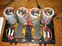
The power supply for my JLH:
Similar to my own, except I used a 300va toroidal transformer and a relay to bypass current limiting resistors used to stop the fuse in the mains plug blowing at switch on.
Many of the well known amplifier brands do not use any form of regulation, instead they use a generously specified transformer and large &/or multiple paralleled (for lower esr) smoothing caps. This is bulkier and more costly than a regulated psu which is why the latter are more popular with cheaper designs.
One more thing to consider is also that some amplifier sound better with SMPS vs the conventionnal transformer w smoothing caps, such amplifier are the extremely popular DIY VSSA. My JLH69 also sound better with a SMPS, a few people on this thread tried SMPS with excellent results.
BR,
Eric
Thank you for that.One more thing to consider is also that some amplifier sound better with SMPS vs the conventionnal transformer w smoothing caps, such amplifier are the extremely popular DIY VSSA. My JLH69 also sound better with a SMPS, a few people on this thread tried SMPS with excellent results.
BR,
Eric
I was wondering about a smps so I will compare the lab psu used for testing with the conventional unregulated one.
I will try it with and without the 47000 smoothing caps to see if it is affected by the large capacitive load.
I will also try some series 0.47r 100watt resistors between the psu & capacitors.
And a few with really dreadful results.a few people on this thread tried SMPS with excellent results.
Member
Joined 2009
Paid Member
you dont need a cap multiplier on the main power rail, its a waste of power. In my version of this amp ( TGM9 thread ) I found that you get most of the PSRR benefits simply from isolating the front end. You can put a low power cap multiplier on the rail to the front end. I found it sufficient to use a resistor and large cap - it is silent.
- Home
- Amplifiers
- Solid State
- JLH 10 Watt class A amplifier