Help me, the UCA202 is a 16-bit device, right?
Also it is specced at 89dB SNR for D/A. How do you get 110dB?
It's normal, the attached document from Analog Device explains it.
Attachments
Pocket Class A - FFT redux
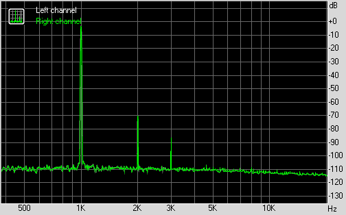
I am using the RCA output of the UCA202 vs the headphone outs this time, and it appears to be cleaner. The FFT now is -70dB for H2 and -90dB for H3. This is a very clean measuring and simple harmonic profile with nothing higher than H3. My ears tell me it sounds very good.
I am using the RCA output of the UCA202 vs the headphone outs this time, and it appears to be cleaner. The FFT now is -70dB for H2 and -90dB for H3. This is a very clean measuring and simple harmonic profile with nothing higher than H3. My ears tell me it sounds very good.
Attachments

It's normal, the attached document from Analog Device explains it.
It does, thank you!
signal is shown as ~-5dBI am using the RCA output of the UCA202 vs the headphone outs this time, and it appears to be cleaner. The FFT now is -70dB for H2 and -90dB for H3. This is a very clean measuring and simple harmonic profile with nothing higher than H3. My ears tell me it sounds very good.
That leaves the 2nd @ ~ -70dB -(-5dB) = ~ -65dB.
Whereas your previous plot gave ~ -67dB - (+6dB) = ~ -73dB
About 1/3rd distortion (8dB less)
I am not sure, but seems to me the cleanliness and simplicity of the above measured harmonic distortion profile perhaps may not have registered with folks. To achieve this with two transistors and a handful of peanuts in parts made in a day blows my mind anyhow. The sound is what it is all about and this amp sounds special.
Only H2 and H3 visible down to the noise floor, I think that's superb! 
Would be an interesting experiment to see how a BJT on the output would compare to the MOSFET's, are you X considering testing any BJT's?
Would be an interesting experiment to see how a BJT on the output would compare to the MOSFET's, are you X considering testing any BJT's?
Last edited:
Only H2 and H3 visible down to the noise floor, I think that's superb!
Would be an interesting experiment to see how a BJT on the output would compare to the MOSFET's, are you X considering testing any BJT's?
Thanks, Maiko - at least two other people think so🙂
I have a similar circuit that Aksa showed me with a BD140 I have been testing but can't get enough gain out of it. Predictions show similar harmonic profile as well. Maybe I need to try a different batch of BD140 with higher Hfe?
BD140, ok I guess you meant this one?
http://www.diyaudio.com/forums/solid-state/301164-mosfet-source-follower-headamp-2.html#post4931474
What I was thinking of was using an NPN (BD139) device as a direct replacement in your current HA running as an emitter follower, and there shouldn't be any gain losses at all, though one thing is the needed base current of the NPN device, if it sucks out too much of the preceeding gain stage, go for BD139-16, hfe = 100-250 according to STmicro.
Are you able to change the test tone frequency in RMAA?
Would be interesting to try a higher frequency and see how H2 and H3 changes, that should give some hint of the sonic signature too.
Drat, I had a brilliant post on this and just lost it when someone distracted me and the finger strayed......
Two topologies. Common source on jfet directly connected to source follower, passively loaded. Second; master nfet directly connected to resistively loaded slave mosfet or bipolar.
Both give high H2 (-60dB) and low H3 (-90dB) and by changing operating point of the jfet of first topology and inserting degen resistor after source of jfet for second topology.
You can see the profile changing with LTSpice. Given that (most ) people rhapsodise about preamp tube amps in common cathode throwing up -45dB of H2, the implication MIGHT be that the more the H2 the better the 'sound', whatever that is.
Certainly the idea of adding distortion is anaethema to self-respecting engineers...... but it has appeal, after all we all like bling don't we?
X has found that his amp is stunning and very engaging for a long listen. He could do a Cmoy design with 0.0015% THD and that would be a wonderful technical job, but it would sound dry, unexciting, and a bit bland.
For myself, I have always recoiled from bland, unexciting sounds. I like a little bling and I've been building amps along this line for 25 years. Oddly, some of my 'best', 'euphonic', and 'engaging' amps, like the Glass Harmony, a tube/mosfet hybrid, had the highest THD levels I had ever measured.
But you couldn't hear it. Actually, it sounded completely clean, like a long, cascading waterfall on a hot day....... and the music was rhapsodic, no question. No feedback, BTW. I really think there is something going on with high levels of global feedback.
So what is going on here? Why is the THD wars the biggest game in town? Who ignores the actual facts, and makes objective sense from the subjective nonsense?
No wonder NP describes audio as entertainment.
HD
If you get a chance Hugh, please post schematic of what you are contrasting above. I redid the measurement a third time. Now with fresh batteries and sitting in a different room. Matches predictions even more. THD according to RightMark is now only 0.012%. Do I need to re-tweak it for more H2? 🙂
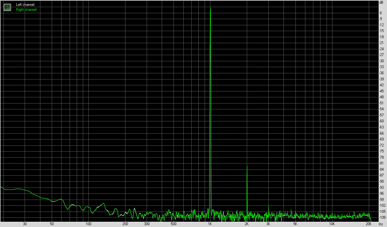
This one is looking superb to me. Practically, pure H2 at roughly -80db. Excellent profile, as well as the absolute level. Great job X 
Thanks Valery. It's really refreshing to listen to this amp. I am not quite sure I would enjoy an amp that has less absolute distortion. But I must find out so Dadod's GW Mk3 is in the queue to be built, and Tomchr's HP-1 is scheduled for a tour to my lab soon. Both amps are in the immeasurable distortion range.
But I must find out so Dadod's GW Mk3 is in the queue to be built, and Tomchr's HP-1 is scheduled for a tour to my lab soon. Both amps are in the immeasurable distortion range.
Hi X,
I was just about to mention the HP-1 audition tour - looks like you're already tuned in. 🙂
Hi X,
I have spent some time tuning my CFP headphone which, when looking through my records, I designed in 2008!!
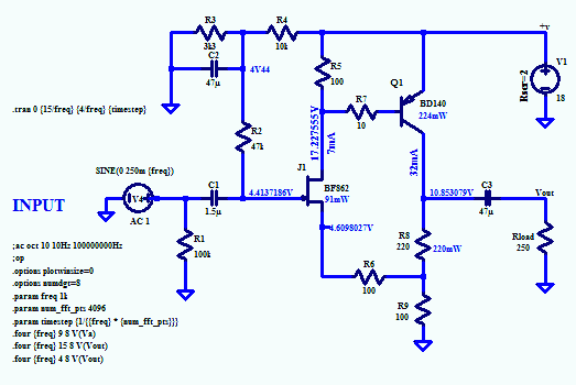
By putting degen onto the source of the nfet, you can increase the H2 whilst reducing slightly the H3. The THD figures are quite high, but 99.8% of the thd is only H2, so it should sound very tubey.
By setting the operating point of the collector of the BD140 slave, you can optimise the dynamic range. I find this starts to distort near clip at around 9Vpp into 280R, and while I have set it at 32mA through the slave and 8mA through the master, it would drive down to 64R headphones very well. For lower impedance cans, you would need to increase the slave current to 80mA, but of course battery life would be much lower. You could also drive this at only a single 12V battery, NiCad or LiH, with slightly less dynamic range.
Advantage: very cheap parts and manipulable distortion profile with just two transistors.
Hugh
I have spent some time tuning my CFP headphone which, when looking through my records, I designed in 2008!!
By putting degen onto the source of the nfet, you can increase the H2 whilst reducing slightly the H3. The THD figures are quite high, but 99.8% of the thd is only H2, so it should sound very tubey.
By setting the operating point of the collector of the BD140 slave, you can optimise the dynamic range. I find this starts to distort near clip at around 9Vpp into 280R, and while I have set it at 32mA through the slave and 8mA through the master, it would drive down to 64R headphones very well. For lower impedance cans, you would need to increase the slave current to 80mA, but of course battery life would be much lower. You could also drive this at only a single 12V battery, NiCad or LiH, with slightly less dynamic range.
Advantage: very cheap parts and manipulable distortion profile with just two transistors.
Hugh
Attachments

I have to try this again and get it to work. Very simple and must found great.
Thanks Hugh.
Can I use 2sk170 vs BF862 to keep it all through hole?
Thanks Hugh.
Can I use 2sk170 vs BF862 to keep it all through hole?
Yes X just try to select one with Idss around 10-12mA.
Note the degen on the source -you dial in the ,
'niceness' you like.....
HD
Note the degen on the source -you dial in the ,
'niceness' you like.....
HD
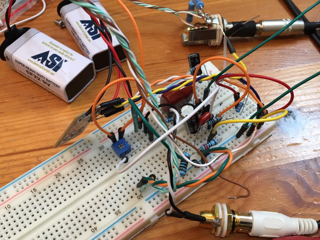
JFET-BJT Headamp with Niceness Knob Works!
Ok, I had some time and thought I would whip this up on a solderless breadboard first as the last time I did it on P2P veroboard it did not work. Well it works well and gets quite loud too so I obviously had something wrong the last time I did it. I am using 2SK170BL and all through hole components this time. I put a 100R trim pot in series with a 47R resistor to get a baseline 100R +/-50R adjustment range for the niceness knob. The solderless breadboard is kind of flakey - noisy with occasional crackles due to poor connections. So I will have to wait for a more permanent amp before measuring FFT and adjusting "niceness" knob. I know it works now so may just go ahead and hand-etch via Sharpie a small PCB for through hole/SMT as the SMT resistors are way easier to solder and require no drilling. I will probably make this as a "tea box" sized amp - a bit bigger than mint tin just because.
Ok, I had some time and thought I would whip this up on a solderless breadboard first as the last time I did it on P2P veroboard it did not work. Well it works well and gets quite loud too so I obviously had something wrong the last time I did it. I am using 2SK170BL and all through hole components this time. I put a 100R trim pot in series with a 47R resistor to get a baseline 100R +/-50R adjustment range for the niceness knob. The solderless breadboard is kind of flakey - noisy with occasional crackles due to poor connections. So I will have to wait for a more permanent amp before measuring FFT and adjusting "niceness" knob. I know it works now so may just go ahead and hand-etch via Sharpie a small PCB for through hole/SMT as the SMT resistors are way easier to solder and require no drilling. I will probably make this as a "tea box" sized amp - a bit bigger than mint tin just because.
Attachments


Last edited:
- Home
- Amplifiers
- Headphone Systems
- MOSFET Source Follower Headamp