Nice work Hugh, X
Could the same amp be done with 2 x 9Vdc battery for a bipolar power supply and get ride of the input/output cap C1, C3. Not sure if a P channel FET exist that could work with BF862...
X, let me know if you want to discard all these cool HA you don't need anymore !
BR,
Eric
Could the same amp be done with 2 x 9Vdc battery for a bipolar power supply and get ride of the input/output cap C1, C3. Not sure if a P channel FET exist that could work with BF862...
X, let me know if you want to discard all these cool HA you don't need anymore !
BR,
Eric
I am sure one could come up with a SE no-cap amp but the DC offset would probably not be stable with two batteries draining at different rates. You would need protection circuit etc, servo for DC offset etc. You would end up with something complicated and not pocket size anymore. The cap doesn't sound bad at all and gives immunity to DC rail mishaps which are all too easy with a loose battery connection.
I am racking up some headamps now and as soon as I figure out which are my main ones I might be able to let some go. I have given away several to good friends already.
I am racking up some headamps now and as soon as I figure out which are my main ones I might be able to let some go. I have given away several to good friends already.
I put a 100R trim pot in series with a 47R resistor to get a baseline 100R +/-50R adjustment range for the niceness knob.
Hi X,
Is that the R6 you are referring to in your schematic?
Thanks
Last edited:
Yes, Syklab.........
I agree with X's comments on the cap coupling. It can be eliminated, but the complexity is a difficult to justify, particularly as a headphone is very sensitive to DC and a cap blocks it wonderfully. I hear now improvement with bipolar, direct connection headphones. Not the same as speakers, however, they need real current but cans are a walk in the park.
Hugh
True, direct connnected headphones to single ended or push pull amps seem to have a bit more high end air. But the differences are not enough to justify he complexity for a small portable amp that has a beautiful sound signature. I have DC coupled output headphones like the amp in post 1 and also, like the Salas DCG3 which I just built. The latter is a wonderdul sounding dynamic amp capable of great levels of authority and splendid high end zing with what I am told is a top end that goes to 3MHz. My frequency response measurement at 96kHz sample shows it is ruler flat to 40kHz anyhow.
http://www.diyaudio.com/forums/anal...g3-preamp-line-headphone-108.html#post4954414
http://www.diyaudio.com/forums/anal...g3-preamp-line-headphone-108.html#post4954414
Last edited:
A few words on capacitors....... mostly for Eric!
Capacitors are charge stores, and until there is a voltage across the electrodes, there is no electrostatic stress on the dielectric. This stress comes from the electrostatic attraction between the electrodes, which is passed mechanically to the dielectric, and it is compressed. It turns out that when AC passes through a capacitor is stresses it first one way (pos to neg) then the other (neg to pos). This swings the stress across the dielectric across the zero point with no stress to the crest (max pos to neg stress) and then to the trough (max neg to pos stress).
There is some evidence in my listening tests that as the dielectric passing through the zero stress point to each way it is quite non-linear, and causes distortion during the 'crossover' point of the bias point. The worst seem to be the electrolytics.
If you bias a cap at an appreciable DC voltage, as we do in this HPA with input and output couplers, we stress the dielectric into the linear area. If the AC pp figure is less than the DC bias, then the dielectric will not pass through the zero stress point; it will always be stress IN ONE DIRECTION, with no 'crossover' point.
I have found that caps of most types respond very well to DC biasing. Consider a tube amp; it might have an AC signal of 30Vpp passing through it, but because of the high DC voltages in those elements it might have 150Vdc across it at all times. People accept caps in tube electronics; it is almost inevitable (unless you use transformers which attract other issues) and for good reason caps are synonymous with tube electronics.
The great advantage of cap coupling on the output is that it blocks DC voltage. Very handy to protect a headphone...... Modern electros with moderate DC bias across them sound very, very good.
Try them - they save a lot of problems, and they do not damage the sound!
HD
Eric, Bangla,
it's actually very easy to adopt well known CFP gain block to dual rail PSU with no coupling capacitors.
In schematic shown below, Q3/R3/R9 make an active load for Q1 - you can use just a 330-390R resistor instead of it - the distortion will be higher but maybe you'll like it.
P1/R8/C1 build the DC-shifter sub-circuit that sets output to 0V DC. (P1 should be multiturn pot.)
Attachments
Last edited:
A few words on capacitors....... mostly for Eric!
Capacitors are charge stores, and until there is a voltage across the electrodes, there is no electrostatic stress on the dielectric. This stress comes from the electrostatic attraction between the electrodes, which is passed mechanically to the dielectric, and it is compressed. It turns out that when AC passes through a capacitor is stresses it first one way (pos to neg) then the other (neg to pos). This swings the stress across the dielectric across the zero point with no stress to the crest (max pos to neg stress) and then to the trough (max neg to pos stress).
There is some evidence in my listening tests that as the dielectric passing through the zero stress point to each way it is quite non-linear, and causes distortion during the 'crossover' point of the bias point. The worst seem to be the electrolytics.
If you bias a cap at an appreciable DC voltage, as we do in this HPA with input and output couplers, we stress the dielectric into the linear area. If the AC pp figure is less than the DC bias, then the dielectric will not pass through the zero stress point; it will always be stress IN ONE DIRECTION, with no 'crossover' point.
I have found that caps of most types respond very well to DC biasing. Consider a tube amp; it might have an AC signal of 30Vpp passing through it, but because of the high DC voltages in those elements it might have 150Vdc across it at all times. People accept caps in tube electronics; it is almost inevitable (unless you use transformers which attract other issues) and for good reason caps are synonymous with tube electronics.
The great advantage of cap coupling on the output is that it blocks DC voltage. Very handy to protect a headphone...... Modern electros with moderate DC bias across them sound very, very good.
Try them - they save a lot of problems, and they do not damage the sound!
HD
Thanks for the great detailed explanation Hugh. I never realized that it was the biasing that keeps the caps in the "class a" region, so to speak. On ceramic caps there is piezoelectric force - so that makes it even worse?
Sorry for my confusing Question.
The Jfet and now plus the Power Jfet is very interesting to learn a bit more here.
For me it would be more interesting: Could be the LU1014 in any combination
be used in Line preamp- so i follow to learn.
Thank you Juma and AKSA and Other for sharing, explanation- i stay half in
forest.....") .....
.....
And yesterday the DCG-3, and lykked has shown a short test with his new
Mini Aleph project in YouTube.
And i came to that what Eric was asking.....
I have no headphone in use.X, let me know if you want to discard all these cool HA you don't need anymore !
The Jfet and now plus the Power Jfet is very interesting to learn a bit more here.
For me it would be more interesting: Could be the LU1014 in any combination
be used in Line preamp- so i follow to learn.
Thank you Juma and AKSA and Other for sharing, explanation- i stay half in
forest.....
.....And yesterday the DCG-3, and lykked has shown a short test with his new
Mini Aleph project in YouTube.
And i came to that what Eric was asking....
.Hi Bangla,
My foray into head amps / preamps was supposed to be a quick excursion. But like all things on diya (speakers, power amps, DAC's, etc), how can you build just one? So about a dozen headamps into it now since starting a few months ago (headamps can be fun and quick to make) I think I am arriving at what I think I like and how they should sound. If you don't have a headphone yet - I can highly recommended the Beyerdynamic DT880-250 special edition chrome. Superb sounding on these headamps. A lot of fun.
My foray into head amps / preamps was supposed to be a quick excursion. But like all things on diya (speakers, power amps, DAC's, etc), how can you build just one? So about a dozen headamps into it now since starting a few months ago (headamps can be fun and quick to make) I think I am arriving at what I think I like and how they should sound. If you don't have a headphone yet - I can highly recommended the Beyerdynamic DT880-250 special edition chrome. Superb sounding on these headamps. A lot of fun.
?But like all things on diya (speakers, power amps, DAC's, etc), how can you build just one
Yup.
And there we are what i call 'A crazy Race' more pain to bring to an issue many
options.
Have to pick more up about LU1014 possible in Line pre.
In my listening Situation i don't need Headphones, will keep in mind your tip.
Distance is like monitoring 2,5m- it's enough mostly 'First Watt' of an amp to
use.
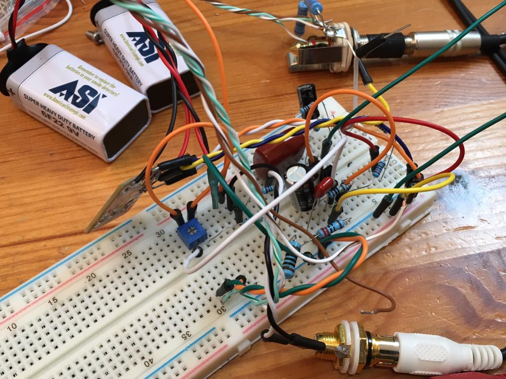
Ok, I had some time and thought I would whip this up on a solderless breadboard first as the last time I did it on P2P veroboard it did not work. Well it works well and gets quite loud too so I obviously had something wrong the last time I did it. I am using 2SK170BL and all through hole components this time. I put a 100R trim pot in series with a 47R resistor to get a baseline 100R +/-50R adjustment range for the niceness knob. The solderless breadboard is kind of flakey - noisy with occasional crackles due to poor connections. So I will have to wait for a more permanent amp before measuring FFT and adjusting "niceness" knob. I know it works now so may just go ahead and hand-etch via Sharpie a small PCB for through hole/SMT as the SMT resistors are way easier to solder and require no drilling. I will probably make this as a "tea box" sized amp - a bit bigger than mint tin just because.
Implementation on PCB with Cap Mx:
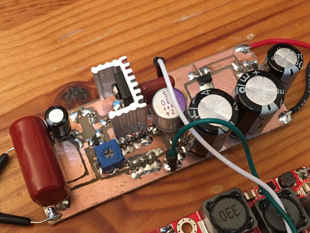
I etched a little PCB using a Sharpie marker to hand draw the layout. This one has a Juma cap multiplier using a ZXMN6A11 SMT MOSFET and a couple of 2200uF caps and a 470uF cap. I even have a niceness knob (100R pot) to dial in the harmonic distortion profile when viewing the output through an RTA.
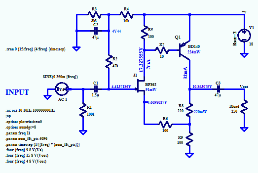
Using a BF862 and BD140 with 2.2uF input coupling cap, and 330uF 25v OSCON output coupling cap with 0.56uF bypass cap.
Just one channel but sounds very nice. Cap multiplier is used to filter the output of a DC-DC converted needed to provide a 20v supply from 5v to 24v input. I am currently running 12v but foresee using 5v USB jack to power this amp. The cap Mx uses the PCB copper as the heatsink. BD140 has local heatsink, SMT resistor banks help spread heat over larger area. Currently running 50 mA bias current.
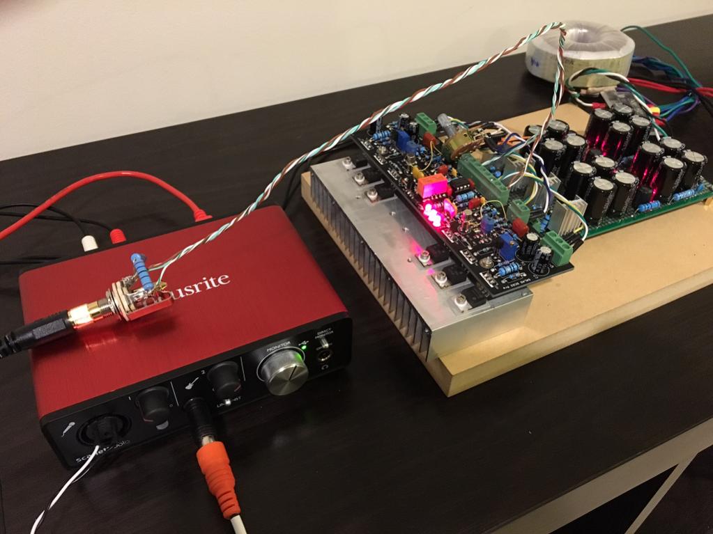
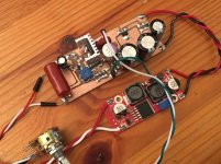
System with cap Mx and DC-DC converter:

Closeup of main amp board:
Attachments

It came up low on bias current (the 4.14v was good) but depending on the Idss (13.3mA on this particular one) of BF862 - I was getting only 40mA through R5. Adjusting the niceness knob changes bias by 2 of 3mA. But I increased supply voltage with D.C. To D.C. Converter and at 20v supply out of cap Mx, bias is 50mA. I will take careful measurement of operating points tomorrow.
Go X!!
We will be really interested in this 'niceness knob'!
I would expect it to range from dry, resolving to 'wet' and lush..... and you could set it for appropriate genre.
Did the LTSpice voltages come up correctly, viz 4V41 and 10V85?
Hugh
Hi Hugh,
I managed to sneak in the lab before departing this morning and got the DC measurements. I readjusted the supply to 18.00v exactly (input of cap Mx is 19.90v so this particular MOSFET on cap Mx has nice low Vgs).
I get values quite close to the simulation (with fluke 101):
4.454v at voltage divider and 4.449v at gate of JFET
17.330v upstream of base stopper of BD140
13.800v at collector of BD140
4.559v at junction of niceness pot (R6) and two power resistors R8 & R9 (200R and 90R actual values). So about 45mAbias current through BD140 and 51.8mA total current through system for 6.8mA bias through the BF862. This is only about 50% Idss so looks like I may need to readadjust 3.3k/10k ratio tongetncloser to 75% Idss for better performance?
Although for my power resistors I am using qnty 5 x 1k for 200R (although I noticed the exact value did not change current through it) and using qnty 4 x 360R for 90R equivalent.
I forgot to measure exact value of niceness pot value but probably 70R is what I think I have it set at.
In general it looks like model of BF862 is pretty good. This particular one has IDSS OF 13.30mA with 18v test voltage and 1k drain resistor.
Last edited:
One question X,
Many thanks BTW, what is the current through the jfet? I'm assuming around 10mA?
Did you assess the subjectives with source degen with 0R, 70R, and 150?
Interesting that you selected HALF the range! WOW!! Do you think it's best FIXED, or VARIABLE?
Sorry, I'm quite keen on this amp, and I'm living vicariously through your testing.......!
Cheers,
Hugh
One question X,
Many thanks BTW, what is the current through the jfet? I'm assuming around 10mA?
Did you assess the subjectives with source degen with 0R, 70R, and 150?
Interesting that you selected HALF the range! WOW!! Do you think it's best FIXED, or VARIABLE?
Sorry, I'm quite keen on this amp, and I'm living vicariously through your testing.......!
Cheers,
Hugh
I think we cross-posted. Current through BF862 was about 6.8mA. I forgot to add a resistor in series my 100R pot - so 100R is the entire range of niceness adjustment at present. It was late and with one test track I could not easily detect an audible difference with one ear and a dance track from Daft Punk playing
i was afraid I would fry something if source seven went to zero ohms?Subjectively so far, it sounds very nice and close to MOSFET version - which is to say, exceedingly nice. I think the gain feels a tad lower as it is not quite as loud. That must be a function of BD140 Hfe? Perhaps cherry pick one with higher Hfe for more gain?
It is very quiet even when running with DC-DC converter and cap Mx. Bass extension is excellent and highs and mids are clear and transparent. No harshness or sibillance detected (I listened to 5 tracks - jazz trio, fenale vocals (2), hip hop dance, rock). Very nice amp from what I know of headamps!

What I am looking forward to is real time tweaking pot to get the perfect (nice) harmonic profile.
Last edited:
- Home
- Amplifiers
- Headphone Systems
- MOSFET Source Follower Headamp