Dude, rather than demanding your requirements, and given that specs ARE important and clearly give a lot of information about how the amp is working, good and bad why don't you trying being positive, and thank X for important, interesting data that many people find useful and drop the negative vibes?
HD
Dude, nobody is demanding anything or being negative.
If acoustic guitar and such is considered state-of-the-art recordings nowadays,
so be it.
Oh yeah...thank you X for the important and interesting data.
Sorry you are unfamiliar with a lot of well-recorded music. If you think it's worthless then don't listen to it. In order to record songs at 320kbit, a maximum of 45 seconds is the limit of the DIYA servers (1.8MB). The September in Montreal clip by Anne Bisson is perhaps one of the finest examples of audio mastering and recording available for hifi systems. Keith Don't Go by Nils Lofgren is another example of a superb recording of instrumental guitar. I would argue that highly produced pop like Natalie Merchant would sound good on any amplifier/speaker. There is a good Eagles rendition of Hotel California.
I have a bunch of threads comparing speakers with this method and I do provide the source tracks so you can compare.
Examples here from Round 3 (I have done like 6 different rounds):
http://www.diyaudio.com/forums/full...ind-comparison-2in-4in-drivers-round-3-a.html
Here are some clips recorded from the new BF862-2SA1837 headamp with source reference tracks for you to compare.
Thanks for the additional clips. I'll download, rename and listen to them when I can.
Adjust R6 Knob for Balanced HD
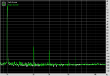
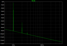
Using a real-time FFT, I adjusted the R6 pot to get the same exact HD components, and adjusted for the H2 to be about 10dB higher than H3. The overall THD increased a bit to 0.0072%, but I think that this gives the best balance for musicality. The overall levels are still quite low with H2 at -86dB and H3 at -96dB and all else at -114dB. The stereo cross-talk is -88.5dB, the IMD is also very good. The dynamic range is 93.5dB, and intermodulation distortion is 0.0032%.
Here is measured FFT with 1kHz and 700mV into 270ohm load (note exact match of harmonic profile of left and right channels - R6 pot is maybe ~30% difference (visually):

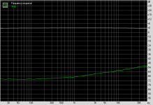
Here is measured IMD:
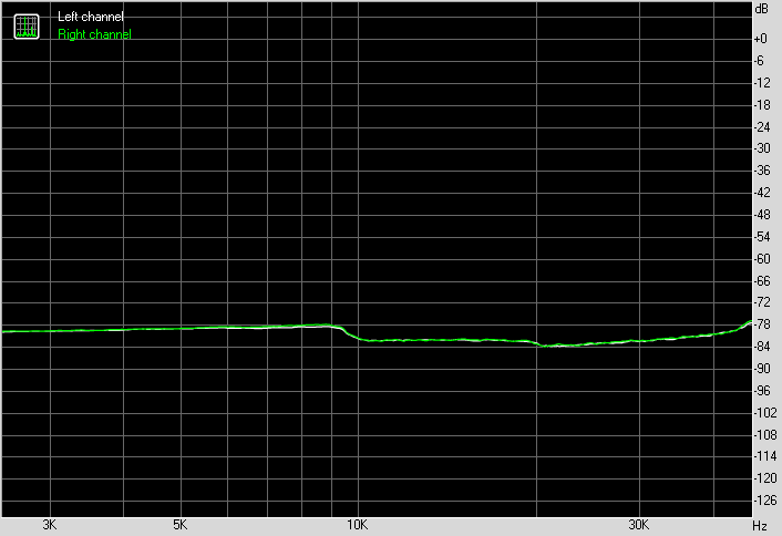
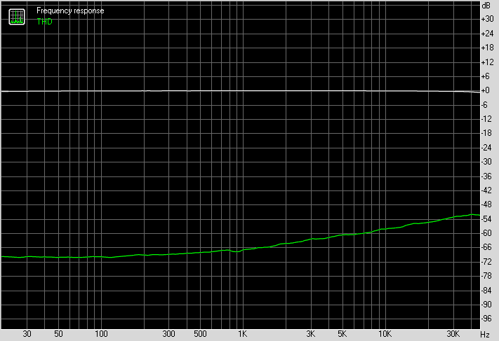
Here is measured Frequency Response and THD vs frequency:
Using a real-time FFT, I adjusted the R6 pot to get the same exact HD components, and adjusted for the H2 to be about 10dB higher than H3. The overall THD increased a bit to 0.0072%, but I think that this gives the best balance for musicality. The overall levels are still quite low with H2 at -86dB and H3 at -96dB and all else at -114dB. The stereo cross-talk is -88.5dB, the IMD is also very good. The dynamic range is 93.5dB, and intermodulation distortion is 0.0032%.
Here is measured FFT with 1kHz and 700mV into 270ohm load (note exact match of harmonic profile of left and right channels - R6 pot is maybe ~30% difference (visually):
Here is measured IMD:
Here is measured Frequency Response and THD vs frequency:
Attachments

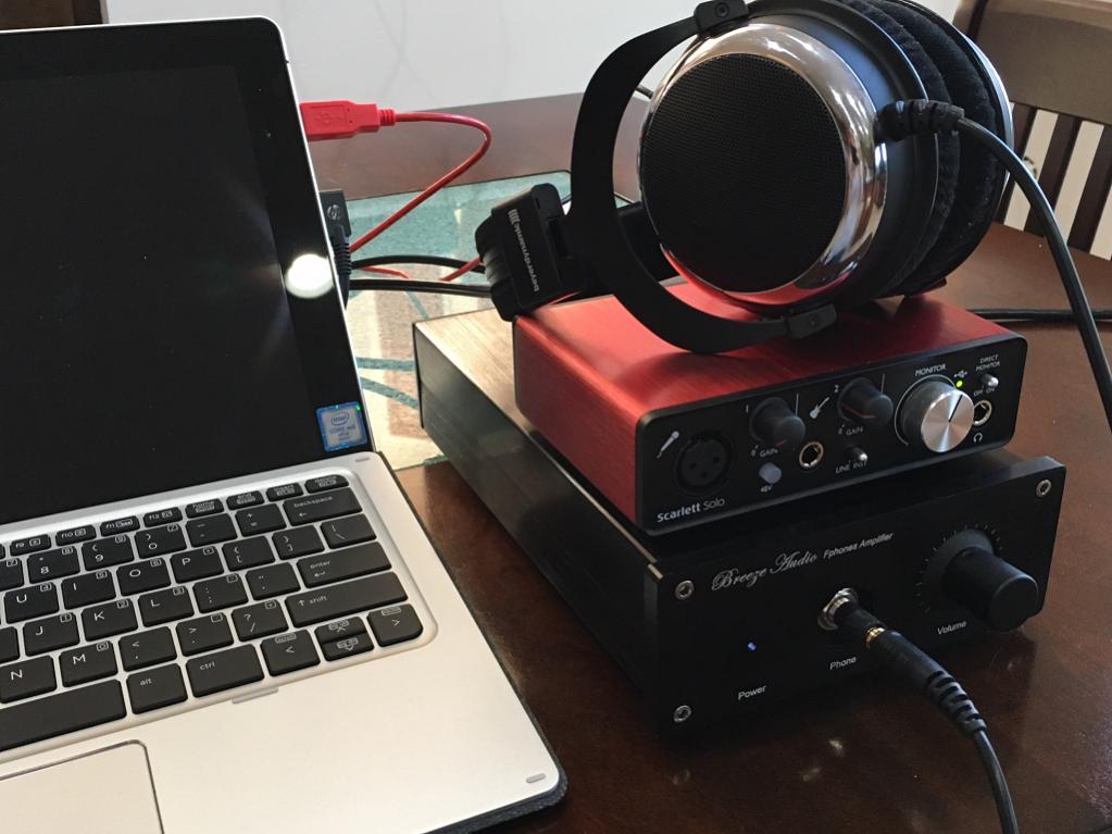
I have been listening for several hours now with this new balanced niceness setting (-86dB H2 and 96dB H3) and it sounds superb. I am using the Focusrite Scarlett Solo 2G as the DAC and it works wonderfully as such - able to get super high speed bit rates, low noise, built in volume control knob, it also has quite a high level output that can drive this amp to very loud sound levels (pain threshold but still clean sounding).
This amp sounds superb and it amazes me how powerful and articulate the bass is for a SE design (not push pull topology). Being always pure Class A, there is of course, never any crossover distortion happening in the 2SA1837. I think this is my new favorite BJT.
This amp sounds superb and it amazes me how powerful and articulate the bass is for a SE design (not push pull topology). Being always pure Class A, there is of course, never any crossover distortion happening in the 2SA1837. I think this is my new favorite BJT.
Mine too, X. These A1837/C4793 complements are arguably the best developed BJTs I have ever used in audio.....
I was amazed at my old proto using a BC546 and a 2SA1837 a couple of years ago; it easily eclipsed my FiiO HPA with a BUF634 double diamond output stage and gave me a tube sound but with utter clarity. Maybe it's better than a 6DJ8 used as a HPA?
Cheers,
HD
I was amazed at my old proto using a BC546 and a 2SA1837 a couple of years ago; it easily eclipsed my FiiO HPA with a BUF634 double diamond output stage and gave me a tube sound but with utter clarity. Maybe it's better than a 6DJ8 used as a HPA?
Cheers,
HD
it easily eclipsed my FiiO HPA with a BUF634 double diamond output stage and gave me a tube sound but with utter clarity.
Dude, just like the "dry sounding" LME49600, the BUF634 is nothing outstanding when it comes to sound quality.
Looks like you finally realized that with that FiiO thingy you purchased.
What exactly is a "tube sound with utter clarity"?
Could this be the "Holy Grail" of HA sound quality? That "ooey gooey" sound of a vacuum tube combined with the clarity of Toshiba's best BJT transistors?

Cheers!
Mine too, X. These A1837/C4793 complements are arguably the best developed BJTs I have ever used in audio.....
I was amazed at my old proto using a BC546 and a 2SA1837 a couple of years ago; it easily eclipsed my FiiO HPA with a BUF634 double diamond output stage and gave me a tube sound but with utter clarity. Maybe it's better than a 6DJ8 used as a HPA?
Cheers,
HD
I just noticed that I can just drop a 2SA1381 in place of the 2SA1387 and I get just about the same thing. In practice, I wonder will it sound just as good?
Hi X,
Yes, you could and it would be faster. Not that you don't more than 2MHz bandwidth!
But the cont Ic is limited to 100mA, and pulsed to 200mA, so you might have to run it at less than 100mA quiescent.
Hi Hugh,
Perfect for portable. So set it similar to last BD140 amp?
Can you please explain process for setting the resistors to achieve the proper DC values? I sort of see by example of what you do but would like to know process otherwise it's much like trial and error in LTSpice for me.
Thanks.
Btw, don't know if anyone noticed but the stereo crosstalk measured for the last 2SA1837 amp had a jaw dropping -88.5dB figure normally associated with true monoblocks with independent power supplies. Here they had common cable feeding both amps. I think having the low ESR cap bank makes the supply seem like it was independent? It was a nice savings of reduced parts count though.
Last edited:
My new reference desktop setup is the 2SA1837 amp now paired with Focusrite Solo 2G as DAC and DT880-250's. Sound is astonishingly good. Operationally perfect: no turn on/off thump, no hiss or noise, can get insanely painfully loud but stay clean, beautiful sound signature...
My new reference desktop setup is the 2SA1837 amp now paired with Focusrite Solo 2G as DAC and DT880-250's. Sound is astonishingly good. Operationally perfect: no turn on/off thump, no hiss or noise, can get insanely painfully loud but stay clean, beautiful sound signature...
Me want too!
First cut at 2SA1381 portable version
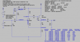
Here is what I am getting so far for the bias settings with the KSA1381/2SA1381. I am having a hard time getting THD less than 1% though. This is with about 50mA bias current. Although HD profile looks really nice...
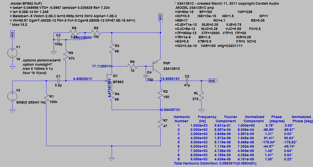
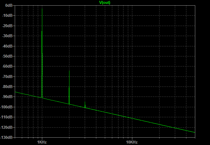
Here is what I am getting so far for the bias settings with the KSA1381/2SA1381. I am having a hard time getting THD less than 1% though. This is with about 50mA bias current. Although HD profile looks really nice...
Attachments
Hi XRK,
You asked about how to set up the DC points.
1. Aim for 12V at the collector of the slave, using Vcc of 18V. This will maximise the output voltage range; the point at which the waveform clips.
2. Chose current through the jfet (master, 10mA) and the pnp (slave, 50mA).
3. Add the device currents through the master and then select the slave resistor, let's select 68R. This will mean (60mA x 68R = 4080mV, ie 4V08 wrt ground.
4. Knowing you will have a gain of 3, select the collector resistor on the slave as (Av - 1)x68. This is 136R, so nearest preferred value would be 150R. The gain will now be (150+68)/68, which is 3.2, around 12dB a good figure for a HPA.
5. Now select the master source resistor. Running 10mA, I would shoot for 68R to your feedback low to profile the harmonics. With the 10mA Id current through this device, it will drop 68Rx10mA = 680mV.
6. The operating voltage reference at the gate of the master will be the 4.08V at the midpoint of the collector string plus the 0.68V dropped across the slave degen resistor minus the Vgs on the jfet, around 150mV, not more. This would then deliver around 4.51V at the gate. This will be very close to the voltage reference on the offside of the gate 47K resistor; since the current into the jfet is very small (3000 times less than a small bipolar running around 10mA Ic). You choose the 10k/3k divider off the supply to create this reference voltage.
7. In practice, your npv of the collector resistor, 150R, is different to the 136R calculated. So you could expect and additional (14R x 50mA = 700mV) on top of the collector voltage; you will have 50mA across this new 150R, which is 7.5V. Add this to your 4.08V and you have 11.75V at the collector of the pnp, bang on!
8. I have chosen 68R at the lower collector string; you chose 47R. Your selection would give you a gain of (150+47)/47 = 4.19. I think this is a bit too high; better would be 150R and 68R.
9. You can adjust the correct voltage, around 12V +/-0.5 at the slave collector by setting a different reference voltage at the jfet gate. This is affected by changing the 3k3 R8 on your LTSpice up or down; a small 5k pot here would be good to set it initially, then fix the resistor when you are happy with it.
A CFP with gain has very low distortion and very easy operating points, quite amenable to simple math. As the gain rises, the local fb drops, and with this the THD rises. The 2SA1381 is a high voltage, low gain, low collector current device and the distortion might be limitations operating it higher than it's designed; the gain bandwidth peaks at about 30mA and the hfe drops at 50mA. This compares to the 2SA1837 which has GB peak at 200mA and hfe starts to drop at 300mA; a more robust animal. In any event, XRK, the THD of 0.0893% is well under 0.1% and 99.9% of this thd is SOLELY H2. I would say this is a warm result, and it should sound very engaging!
Hugh
Last edited:
Hi Hugh,
Thank you so much for the detailed explanation on how to calculate the set points. I got close by trial and error and now much better to know the steps. I will have to re-read and do a few examples for this to sink in fully. This post is definitely another one of your many gems! It seems that there is not much to be gained by going with 2SA1831 but loss of current headroom and larger size. If I can still get the 1837, perhaps best to stick with it then for best sound, even at 50mA bias.
Thanks again.
X
Last edited:
I wonder if my extensive use of SMT components and very small tight layouts has something to do with how clean and quiet the amps are? Less room for noise pickup and connections between components are short, and SMT parts are high quality and inherently low self-inductance. Would a larger through hole amp with the same circuit fare as well?
XRK,
I goofed a few times! Here's a retake:
1. Aim for 2/3 Vcc at the collector of the slave. For Vcc of 18V. This will maximise the output voltage range with 12V at C of slave; this sets the highest waveform clip.
2. Choose a suitable current through the jfet (master, 10mA) and the pnp (slave, 50mA). The jfet current should be 2/3 of the Idss, while the pnp current is determined by the lowest impedance load you wish to drive. 16R cans need around 150mA.
3. Add the save current to the master current (10+50) and then select the slave resistor, let's select 68R. This will drop (60mA x 68R) = 4080mV, ie 4V08 wrt ground.
4. Knowing you will have a gain (Av) of 3, select the collector resistor on the slave as (Av - 1)x68. This is 136R, so nearest preferred value would be 150R. The gain will now be (150+68)/68, which is 3.2, around 10dB a good figure for a HPA.
5. Now select the source degeneration resistor. Running 10mA, I would shoot for 68R to your feedback low to profile the harmonics. With the 10mA Id current through this device, it will drop 68Rx10mA = 680mV, making the source (0.68+4.08) = 4.76V wrt ground.
6. The operating voltage reference at the gate of the master will be the 4.08V at the midpoint of the collector string plus the 0.68V dropped across the slave degen resistor minus the Vgs on the jfet, around 150mV, not more. This would then deliver around 4.51V at the gate. This will be very close to the voltage reference on the offside of the gate 47K resistor; since the current into the jfet is very small (3000 times less than a small bipolar running around 10mA Ic). You choose the 10k/3k3 divider off the supply to create this reference voltage as a start; trim it empirically after you have it running.
7. In practice, your npv of the collector resistor, 150R, is different to the 136R calculated. So you could expect and additional (14R x 50mA = 700mV) on top of the collector voltage; you will have 50mA across this new 150R, which is 7.5V. Add this to your 4.08V and you have 11.75V at the collector of the pnp, bang on!
8. I have chosen 68R at the lower collector string; you chose 47R. Your selection would give you a gain of (150+47)/47 = 4.19. I think this is a bit too high; better would be 150R and 68R.
9. You can adjust the correct voltage, around 12V +/-0.5 at the slave collector by setting a different reference voltage at the jfet gate. This is affected by changing the 3k3 R8 on your LTSpice up or down; a small 5k pot here would be good to set it initially, then fix the resistor when you are happy with it.
on those picture above, i see an input capacitor > 1,5uF with red color and huge size
but, can you tell me what is its voltage???
I just happened to have some 2.2uF (250v or 400v can't remember) MKT caps (CBB brand from China) on hand. A Wima MKS or MKP 50v or 63v should work nicely here.
But then maybe the high voltage rating has something to do with the sound?
Last edited:
- Home
- Amplifiers
- Headphone Systems
- MOSFET Source Follower Headamp