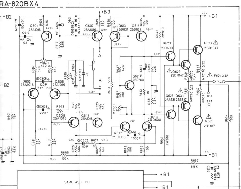
Typical 3 stage gain "Sansui type" High Ft classic amp.
What is weird , they use a phase inverted driver stage (diamond like)
and then use positive feedback.
(below)
The NFB version of this amp (sansui) . is typically 20ppm-20k.
That is , with faster 35mhz sanken outputs.
OS
This draws very much from the Matti Otala Low TIM amp.
Not the subject of this thread but thought I'd mention it.
RA-820AX peculiar fault
well it's peculiar to me anyway. I am recapping one of these and there is a hum that ONLY occurs when the balance control is half way left or right, NO hum when it is in the middle or fully right or left. The hum is on the opposite speaker to the balance setting. It is there when the volume is fully off and does not increase with volume, the music will drown out the hum! any ideas as to were to look? I've tried resoldering, it also gets slightly louder when I touch the chassis, but this does not have an earth wire to the mains
well it's peculiar to me anyway. I am recapping one of these and there is a hum that ONLY occurs when the balance control is half way left or right, NO hum when it is in the middle or fully right or left. The hum is on the opposite speaker to the balance setting. It is there when the volume is fully off and does not increase with volume, the music will drown out the hum! any ideas as to were to look? I've tried resoldering, it also gets slightly louder when I touch the chassis, but this does not have an earth wire to the mains
posted a new thread on this:
http://www.diyaudio.com/forums/solid-state/306077-rotel-ra-820ax-peculiar-fault.html
http://www.diyaudio.com/forums/solid-state/306077-rotel-ra-820ax-peculiar-fault.html
Hello again y'all!
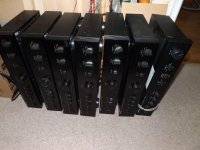
After a long hiatus due to work, the row of Rotels waiting for me to upgrade is now getting rather embarrassing - and their owners increasingly (albeit understandable) impatient.
So, I decided to finally stop doing the very time consuming fumble-boarding of the CM and VAS circuits, and instead design and order proper double sided SMT boards from PCBway - which I must say I have had very good experiences with in the past.
At first I decided to also ask PCBway to populate the pcb's for me, but the initial web price quote for this simple job suddenly almost doubled and it appeared that someone in their procurement considered a 100k 1% resistor chip as a good match for the specified 100E 0.1% (!)
So, I sort of lost confidence and thought "Ok, I can do this better and cheaper". Well.....
After some experimenting and getting to a decent solder paste stencil printing setup result, I first tried to solder the small pcb's with my trusted SMD hot air gun.
I still have to locate some of the the boards and most of the tiny 0603 components somewhere on the floor.
So, I bought a cheap T-962 IR reflow oven, which, after having done all the essential safety repairs and firmware upgrades as recommended on the web, now performs very nicely indeed.
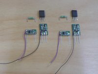
My first finished miniature boards of the CM and VAS are pictured under the original components for which they will be a direct drop-in replacement.
But a DYI'ers troubles never stop there. Stay tuned!
After a long hiatus due to work, the row of Rotels waiting for me to upgrade is now getting rather embarrassing - and their owners increasingly (albeit understandable) impatient.
So, I decided to finally stop doing the very time consuming fumble-boarding of the CM and VAS circuits, and instead design and order proper double sided SMT boards from PCBway - which I must say I have had very good experiences with in the past.
At first I decided to also ask PCBway to populate the pcb's for me, but the initial web price quote for this simple job suddenly almost doubled and it appeared that someone in their procurement considered a 100k 1% resistor chip as a good match for the specified 100E 0.1% (!)
So, I sort of lost confidence and thought "Ok, I can do this better and cheaper". Well.....
After some experimenting and getting to a decent solder paste stencil printing setup result, I first tried to solder the small pcb's with my trusted SMD hot air gun.
I still have to locate some of the the boards and most of the tiny 0603 components somewhere on the floor
. So, I bought a cheap T-962 IR reflow oven, which, after having done all the essential safety repairs and firmware upgrades as recommended on the web, now performs very nicely indeed.
My first finished miniature boards of the CM and VAS are pictured under the original components for which they will be a direct drop-in replacement.
But a DYI'ers troubles never stop there. Stay tuned!
Attachments
The Pioneer SX780 provides an excellent platform for improvement as the tuner can be modded with an op amp output instead of the 2SA7xx transsitors, it regulates the amplifier VAS stage and double regulates the Phono and preamp sections.
I am adding in the Lichstark-x mosfet amp , Volume preamp ,6922 tube preamp and new phono stage. This unit is easy to work on as it opens up easily.
new amp puts out 75w peak before clipping with 22000uf Caps
early tests indicate phenomenal sound quality.
I am adding in the Lichstark-x mosfet amp , Volume preamp ,6922 tube preamp and new phono stage. This unit is easy to work on as it opens up easily.
new amp puts out 75w peak before clipping with 22000uf Caps
early tests indicate phenomenal sound quality.
Last edited:
Hi AngelP,
I was wondering if your mod would apply to a Rotel Rx-950ax? the amp section does look close to yours but not exactly the same.
Thanks
Hi memofer,
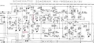
I have never been under the bonnet of a Rx-950ax, but had a brief look at the schematic of the power amp stage. The diff PNP input could definitely be improved with properly paired 2SA992's and a current mirror instead of their two collector resistors. I would also short out the strange single 47k emitter resistor that clearly unbalances the input and is a proper noise source.
For the VAS section, my small pbc module contains all the 950ax circuitry, but also includes the important pre-VAS emitter follower. It will not quite be a direct drop-in replacement as in the RA-930 series, but the mod should be doable with a bit of tweaking of the pcb's "collector" pin connection.
Maybe you should attach the RX-950ax amp section schematic for other DIYers to be able to follow?
Cheers,
Per
But a DYI'ers troubles never stop there. Stay tuned!
As readers of this thread may know, I have a setup of a dummy load box with a built-in XonarU7 audio to USB unit which makes RTA of amps very quick and easy.
Due to other work I had it stacked away for quite some time, but having finished the new pcb modules I was very eager to set it back up and do pre- and post mod measurements. Too eager.
I forgot to attach my trusted USB isolator (pictured) to the cable, and the first RA-931 patient I connected - had 120Vac stray voltage on the speaker outputs. Not much energy in it, but enough to feel a small tingle when touching the outputs and the PC enclosure.
And enough to show the weakest link in the setup - the Xonar's USB com circuitry, which apparently does not have a proper overvoltage protection.
I now have an invisible XonarU7 box - at least to any USB port.

Attachments

Interesting. I currently have an old RB960BX on the kitchen table and have been considering some tweaks. My first thought was to add a current mirror to the input stage. It will be interesting to follow your progress.
I have a RA 970BX . Wonder if these are partially similar ?
I have a RA 970BX . Wonder if these are partially similar ?
The RA-970BX power amp stage is different from the RA-300 series. It has extensive symmetrical NPN/PNP input and VAS stages, which looks promising as an idea, but eventually the specs were actually no better than e.g. the RA-931.
Hi memofer,
I have never been under the bonnet of a Rx-950ax, but had a brief look at the schematic of the power amp stage. The diff PNP input could definitely be improved with properly paired 2SA992's and a current mirror instead of their two collector resistors. I would also short out the strange single 47k emitter resistor that clearly unbalances the input and is a proper noise source.
For the VAS section, my small pbc module contains all the 950ax circuitry, but also includes the important pre-VAS emitter follower. It will not quite be a direct drop-in replacement as in the RA-930 series, but the mod should be doable with a bit of tweaking of the pcb's "collector" pin connection.
Maybe you should attach the RX-950ax amp section schematic for other DIYers to be able to follow?
Cheers,
Per
Thanks for the suggestion AngelP, I will check it out as soon as I can and will apply some of your modifications. Though, I am still learning about amplifiers, I am not sure how difficult it will be to apply the Current Mirror you suggest. will that single modification makes that much difference? as I have never had an amp. that uses current mirror.
and by-the-way, I want to thank you for making this info available as I like my Rotel receiver, I know it can be improved.
thanks,
Hi again AngelP,
Your name is most appropiate for me, because your single suggestion re removing the 47k emitter resistor, and including some of your other mods,
has made a huge difference. it almost feels like you just handed me a completely different amp! it sounds better than I expected and I will
have to go over my music library again!
Now, I am really curious about the current mirror and will research to see how I can apply it, would you be willing to sell me the parts?
or suggest what to buy?
For now, I will enjoy it as much as I can.
attached are the changes I made.
Thanks,
Attachments
Hi memofer,
Congrats with your success so far! I would probably have placed the two 150E resistors on the other side of the Q619/621 driver collectors so they wouldn't have to carry the extra current and voltage drop, but that's just me.
You can of course make the current mirror yourself, but it is a bit of a fiddle because the mirror transistors are SMD's. (See pic in 264)
Having already had the pcb's professionally made and bought the components, it would absolutely make sense to populate and reflow solder the parts for you and other modders. Further, I will sell them at cost, as this is my passion - not my day job.
The current mirror mod job is now made very easy, just remove R615 and R617, drop in and solder the CM module in place of R615 (resistor end down to V-) and solder the thin wire from the module to the top end of the R617 pad where it connected to the Q605 collector - and repeat for the right channel.
For the VAS module, I will have to look again on your amp layout, but it seems relatively easy. Remove C607, Q613 andQ 615. Drop the VAS module in place of Q613 and short R629.
The black wire from the module should be soldered to ground, possibly to the ground end of R609.
All these mods are reversible - no cutting of pcb tracks, etc.
That's great!
I am most definitely interested in buying those 2 modules from you as you have made it very easy to install,
just let me know when you have them ready and we'll close the deal!
re those 2 resistors, the only reason I placed them there was because, it was just to easy to do it
at that locaion, as all I had to do was to remove 2 jumper link wires and bingo! it was so easy. so far they
seem just fine as they don't even get warm, so it must be ok.
Looking at the layout, would you know what is the purpose of Q609? just curious!
Let me know!
Cheers!
Q609 and all the circuitry around it forms a constant current sink from the bases of Q607/611 down to V- - replacing the simple 6k8 resistor to ground usually found in that place.
Is it better, does it really improve things? - well, I don't know, I've never measured it.
Mind you, it could be a good idea for the purpose of increasing PSRR, but I think that your nice, brutal 150E / 100uF filters do the job just as well.
You know, sometimes I have the feeling that Curtis may have been under pressure to do "something (anything) new" for Rotel's marketing of new models.
As far as I know, the only difference between RA-391 and RA-391 mkII was the replacement of the preamp's NE5532 to the OPA2604.
The RA-970BX power amp stage is different from the RA-300 series. It has extensive symmetrical NPN/PNP input and VAS stages, which looks promising as an idea, but eventually the specs were actually no better than e.g. the RA-931.
Yes, I looked at the circuit diagram this morning. It will be interesting to see if the amp 'sounds' any better or worse after making it dc coupled like I did with the RA-01. Hopefully I can do that this weekend.
Don't really want to do much chopping of tracks etc.I'm not comfortable with that. I'll stop when it starts getting complex. There are a lot of other power amp boards to compare them by. Been waiting to get enough time to do that.
Hi ashok,
I truly admire your "just do it" attitude and your appetite to investigate what mods work. Also, your considerations for your speakers' welfare - that is very prudent and I would strongly suggest that you use 8 ohm dummy loads while experimenting. Your bank manager will love you for it!
I DC coupled the RA-820AX at the start of this thread and it does sound absolutely great and (slightly further) reduced THD. But it also gave a ton of work in redesigning the tone circuit values to ensure that the DC load to the power stage input remained unchanged when shifting between tone and direct.
Also, you really never know in what hands or setup the amp will eventually end up, so I would recommend that you keep the DC cap block at the preamp input to avoid causing other people the misery of smoking speakers.
Just my 2p.
Q609 and all the circuitry around it forms a constant current sink from the bases of Q607/611 down to V- - replacing the simple 6k8 resistor to ground usually found in that place.
Is it better, does it really improve things? - well, I don't know, I've never measured it.
Mind you, it could be a good idea for the purpose of increasing PSRR, but I think that your nice, brutal 150E / 100uF filters do the job just as well.
You know, sometimes I have the feeling that Curtis may have been under pressure to do "something (anything) new" for Rotel's marketing of new models.
As far as I know, the only difference between RA-391 and RA-391 mkII was the replacement of the preamp's NE5532 to the OPA2604.
I was not planning on doing anything to it, just wasn't sure of it's purpose, but that makes sense as a constant current sink, I thought it was some sort of voltage divider/regulator.
I used those 150E resistors cause it was all I had in my parts bin and I figure it was close enough! so maybe I just got lucky!
I know what you mean, there is another model of the 950ax that is the mkII,
but I have no clue what's the difference, maybe it is as the one you mention.
though, in my amp. the schematic is wrong on resistor R613 47k, as it was only 47ohms not 47k. maybe just a typo.
Oh, that would make so much more sense, 47E would be an attempt of an emitter degrading resistor - but which should have been 0.1% mirrored in the other input transistor pair branch - or shorted out.
47k would be absolutely bonkers!
Are you contemplating putting in a new hFE matched input pair, or are the existing trannies ok matched? Do you know?
47k would be absolutely bonkers!
Are you contemplating putting in a new hFE matched input pair, or are the existing trannies ok matched? Do you know?
- Home
- Amplifiers
- Solid State
- Improve a Rotel amp THD by 20dB!