The Arduino platform are fairly easy to program once you get the hang of it. Solar project nearing completion. Analog protection circuits work just as well for amplifier protection, the SS relay option looks good.
All of our protection circuits are actually analog, we just monitor them digitally and make them all work together with the microcontroller.
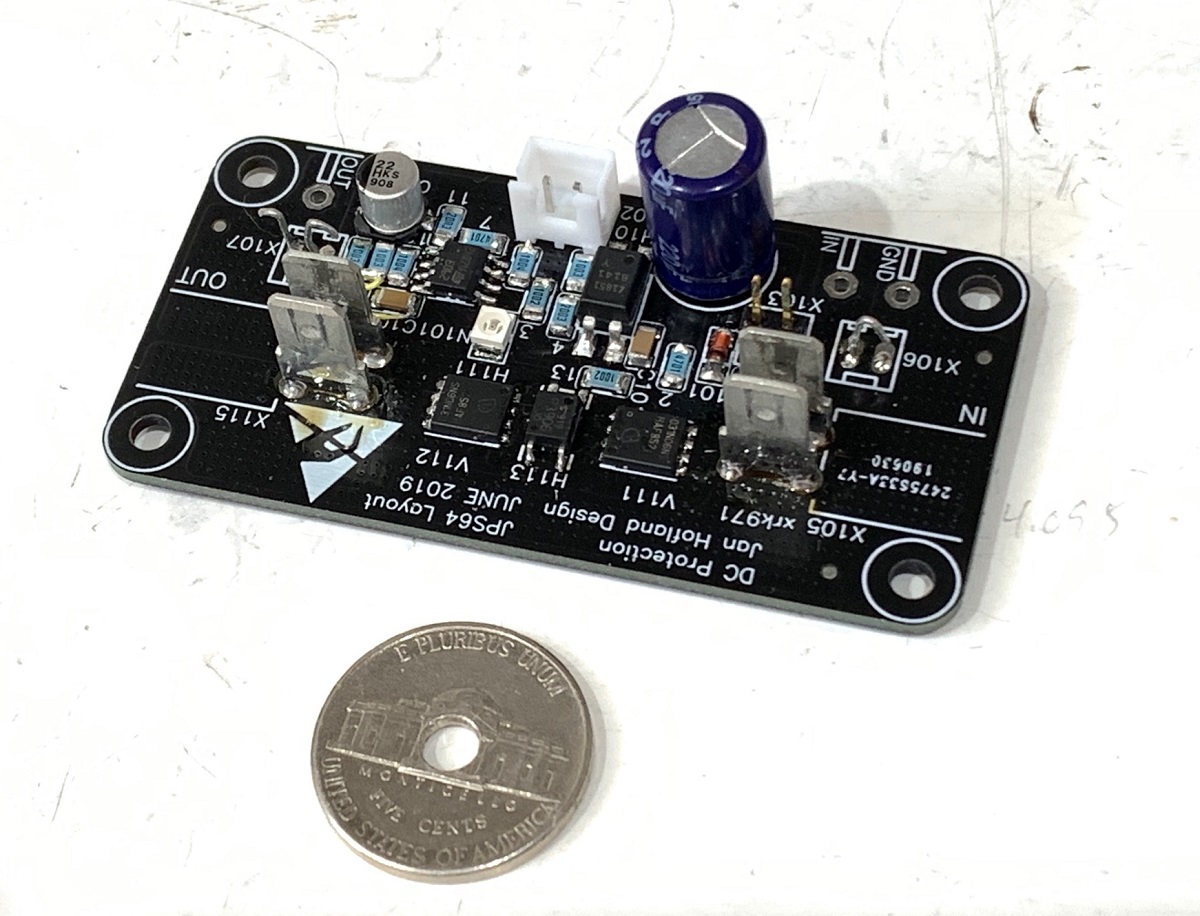
I just tested Jhofland’s SSR protection circuit with Valery’s VHEX+ and got some great results. The SSR really does act like a wire - no added distortions.
Ready-to-Run (RTR) SSR DC Speaker Protection and Delay GB
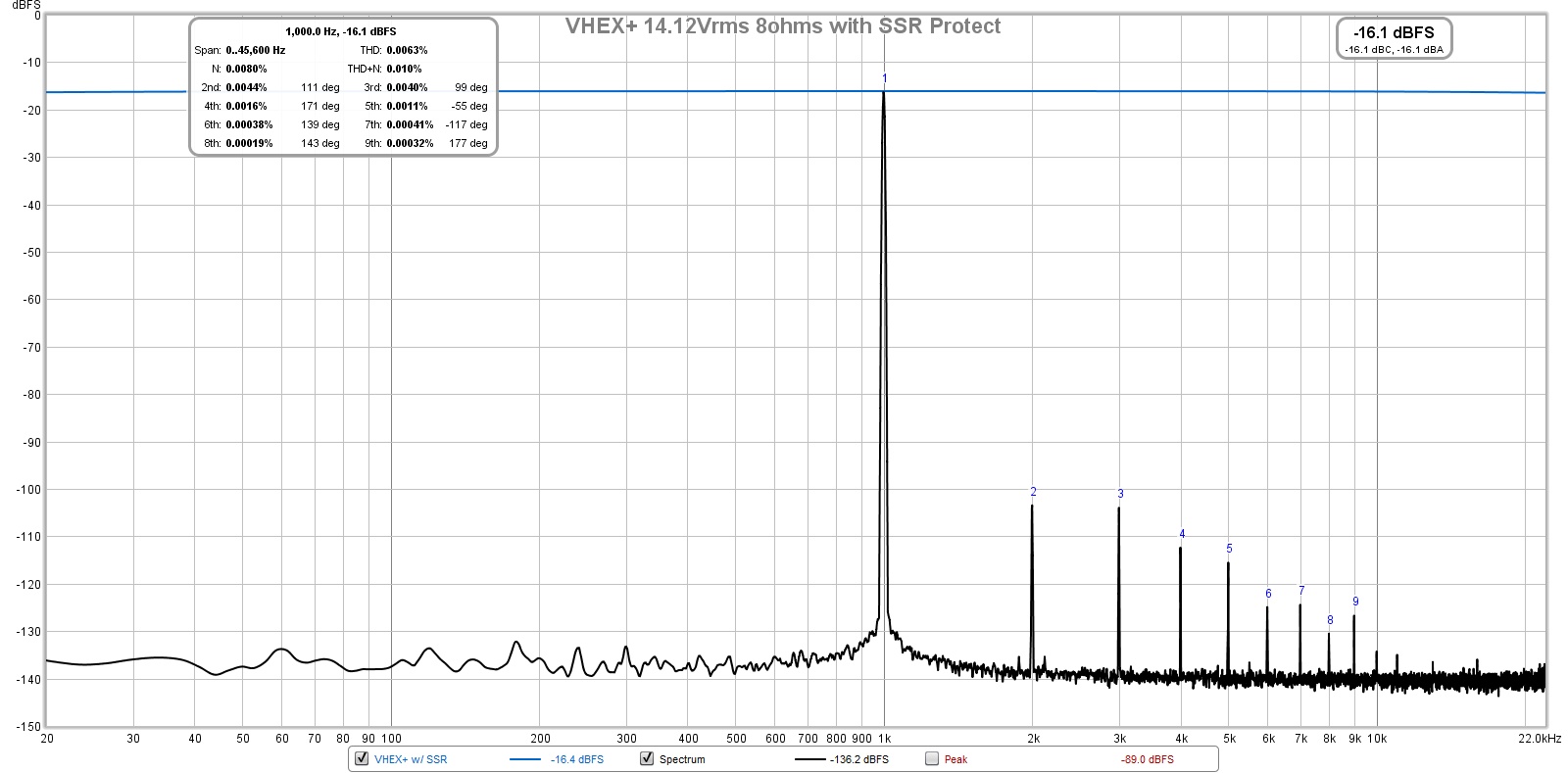
Here is THD with and without SSR at 25wrms into 8ohms.

Here are the FFTs at 25wrms with and without:
With SSR:
Without SSR:
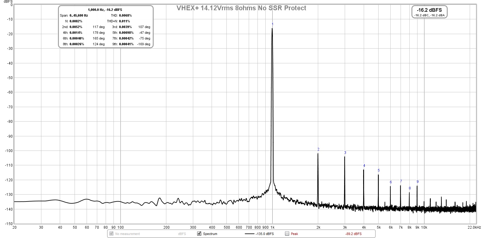
The VHEX+ sounds great - very low noise as you can see from the FFTs.
Ready-to-Run (RTR) SSR DC Speaker Protection and Delay GB
Here is THD with and without SSR at 25wrms into 8ohms.
Here are the FFTs at 25wrms with and without:
With SSR:
Without SSR:
The VHEX+ sounds great - very low noise as you can see from the FFTs.
Good work - a very useful test. SS relays are great. Fast, reliable, and - as we can see - "transparent" for the signal. Literally - like a wire.
Neat board, by the way - nice "minimal" speaker protection.
Just as an idea for the next version - adding just one more connector will allow controlling the rails of our Compact PSU board. As soon as protection fires, it will not only disconnect the speakers, but will also disconnect the amplifier board from PSU (the rails are also controlled by SS relays), protecting the amplifier as well (minimizing the possible damage).
P.S. We will also have to add one more connector as right now the Compact PSU board is designed for i2c control bus")
Neat board, by the way - nice "minimal" speaker protection.
Just as an idea for the next version - adding just one more connector will allow controlling the rails of our Compact PSU board. As soon as protection fires, it will not only disconnect the speakers, but will also disconnect the amplifier board from PSU (the rails are also controlled by SS relays), protecting the amplifier as well (minimizing the possible damage).
P.S. We will also have to add one more connector as right now the Compact PSU board is designed for i2c control bus
Last edited:
This unit is powered by the amp’s own +ve rail. Not sure if we want to remove its own self power. Then it can’t come back on. Maybe a separate protector unit could be made to sense too much current and disconnect itself like a fuse? Circuit would be committing temporary suicide until a reset button is pushed.
Ok, I misunderstood and thought you meant disconnect PSU from mains. That could be done with a triac but would need separate small 12v wall-wart PSU. Aren’t fuses between the PSU and amp sufficient for most problems?
What would be neat is a digital input to allow remotely controlled muting function where the speakers are manually disconnected from some app via WiFi Arduino NodeMCU. Same app can also handle digital volume control on the signal input my a Maxim digital pot via I2C.
What would be neat is a digital input to allow remotely controlled muting function where the speakers are manually disconnected from some app via WiFi Arduino NodeMCU. Same app can also handle digital volume control on the signal input my a Maxim digital pot via I2C.
Hi Harry,
I will take a liberty to answer - you're right, in both cases, the cathodes (pins 5, 7) have to be connected to the gates. BTW, the optocoupler's outputs don't necessarily have to be paralleled - in the latest version of the PSU board we use a single optocoupler to control both + and - rails.
Cheers,
Valery
The early schematics using the ASSR optocouplers are often incorrect. I downloaded a component for Diptrace that was drawn incorrectly which caused lots of mistakes and confusion until I figured out what was wrong. I've since learned out how to create my own components.
So just to clarify this - is the -ve rail diagram in the referenced post #737 both connected incorrectly and drawn incorrectly? The ASSR-V622 (contra the ASSR-V621) has cathode on pins 6 & 8, which I believe should each be connected to the drain of the MOSFET, not the gate.
The ASSR-V621 on the +ve rail is drawn correctly, according to the datasheet, however I think it too is connected incorrectly. It would have -7V between the gate to source connected in that fashion so it would not work as intended.
Incidentally, I noticed the ASSR-V622 as drawn in the DC detect v4.3 build guide is also drawn incorrectly, but it appear to be wired correctly.
What is the newer version ?
May I have a copy?
Are you looking for the speaker relay build guide?
The build guides are available through our website. Just register on our site( no charge, no purchase necessary) and Valery will open up the download section for you.
We have a couple new control board designs in testing right now. Build guides should be available for them in the next couple weeks.
We have a couple new control board designs in testing right now. Build guides should be available for them in the next couple weeks.
- Status
- This old topic is closed. If you want to reopen this topic, contact a moderator using the "Report Post" button.
- Home
- Amplifiers
- Solid State
- How to build a 21st century protection board