The current detection circuit is meant to operate with rail fuses in place. The rail fuses are sized to protect the transformer and rectifier. The current detection circuit is meant to be sized to keep the output transistors in their SOA range. If it were sized to limit average current it would constantly false trigger due to the speed of detection. There is a tremendous amount of current available from the supply capacitors. The detection circuit is protecting against that, not the transformers current.
Right - switching off the rails also lead to shutting down the amp - this is an "emergency" situation, far beyond the normal operation conditions.
So, unlike the U/I limiter, that limits the currents through the output devices at some reasonable level, our current sensor initiates switching off the rails and shutting down the amp if any output transistor's emitter current exceeds around 5A - at this level, transistors are still within the SOA, but definitely above the normal operation conditions.
So, unlike the U/I limiter, that limits the currents through the output devices at some reasonable level, our current sensor initiates switching off the rails and shutting down the amp if any output transistor's emitter current exceeds around 5A - at this level, transistors are still within the SOA, but definitely above the normal operation conditions.
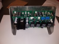
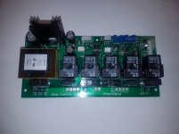
I have a new version of the dual supply control board running. The AC voltage loss detection circuit has been redesigned. It now uses an optoisolator instead of the soon to be obsolete detector IC. I designed this one to stack on top of a pair of power supplies for our NS-OPS amplifiers, so it's a bit larger. it makes for a very nice power package, and should go nicely with the NS-OPS amplifier boards with integrated speaker relays and sensors. It will still work with any other amplifier too.
Attachments
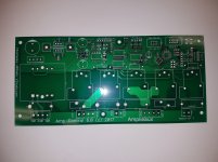
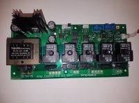
The AC voltage loss detection circuit has been redesigned. It now uses an optoisolator instead of the soon to be obsolete detector IC.
Could you post the circuit and component numbers for the redesigned AC voltage loss detection.
The new PCB looks excellent. Putting all five relays in a row helps wiring when this PCB is screwed onto the rear amplifier panel.
I think I've come up with a good way to interface the amp control board with external devices to show states of operation and error codes without adding any real overhead to the amp control processor. There are four available analog pins in the ATMEGA328 (A4 and A5 are used for I2C communications). That would allow me to write a 4 bit message, or up to 16 different state / error messages to be interpreted by an external device.
I'm going to test this idea in my Double Barrel NS-OPS monoblock builds for interfacing with a front panel display. These amps will also be a test bed for wireless remote power on trigger.
I'm going to test this idea in my Double Barrel NS-OPS monoblock builds for interfacing with a front panel display. These amps will also be a test bed for wireless remote power on trigger.
Advanced options in the DIY world!I think I've come up with a good way to interface the amp control board with external devices to show states of operation and error codes without adding any real overhead to the amp control processor. There are four available analog pins in the ATMEGA328 (A4 and A5 are used for I2C communications). That would allow me to write a 4 bit message, or up to 16 different state / error messages to be interpreted by an external device.
I'm going to test this idea in my Double Barrel NS-OPS monoblock builds for interfacing with a front panel display. These amps will also be a test bed for wireless remote power on trigger.
Good work Jeff!
")
Thanks Thimios.
I've written a basic protocol I plan to use for the first test.
0000 - off
0001 - tube preheat
0010 - 1st supply inrush
0011 - second supply inrush
0100 - power on
0101 - speakers on
0111 -
1000 - DC Offset
1001 - overload
1010 - AC Failure
1011 - overtemp 1
1100 - overtemp 2
1101 -
1110 -
1111 -
This would be simple to read with a port expander.
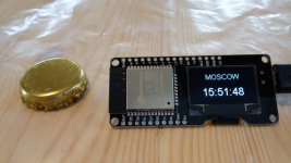
For the same purpose, I've started experimenting with a tiny front-panel module, incorporating a 32-bit processor, OLED display, WiFi module and some input/output pins. Beer bottle cap is placed nearby as a scale - the board is really compact, worth $10 USD.
My first test sketch does the following:
1) Connects to the internet via local WiFi;
2) Communicates with NTP server, receiving the packet;
3) Syncs its internal clock with NTP time from the packet;
4) Calculates the timezone and shows correct time on the display, updating it once in a second.
The thing is very fast and versatile, so now we will likely start using it for indicating the soft-start sequence phases, error codes, heatsink temperatures, as well as logging telemetry at the web portal.
We're moving deeper into the 21-st century guys
Attachments
Hi Valery,i'm sure that you can move deeper,your application engineer Jeff is the right person in the right position!For the same purpose, I've started experimenting with a tiny front-panel module, incorporating a 32-bit processor, OLED display, WiFi module and some input/output pins. Beer bottle cap is placed nearby as a scale - the board is really compact, worth $10 USD.
My first test sketch does the following:
1) Connects to the internet via local WiFi;
2) Communicates with NTP server, receiving the packet;
3) Syncs its internal clock with NTP time from the packet;
4) Calculates the timezone and shows correct time on the display, updating it once in a second.
The thing is very fast and versatile, so now we will likely start using it for indicating the soft-start sequence phases, error codes, heatsink temperatures, as well as logging telemetry at the web portal.
We're moving deeper into the 21-st century guys
Many projects at the same time!Amp control 6.01 is ready to power up. This one has connections for data logging. Let the fun begin!
Perfect!
Are you planning to etch one yourself?
Hi Jeff
When you have time can you please check the schematic in post 737?
I think the opto coupler on the negative supply is not correctly connected to the MOSFET gate. The PCB is OK.
Thanks
Harry
PS I realise you have parallelled the opto on the PCB and the schematic is slightly different.
Hi Jeff
When you have time can you please check the schematic in post 737?
I think the opto coupler on the negative supply is not correctly connected to the MOSFET gate. The PCB is OK.
Thanks
Harry
PS I realise you have parallelled the opto on the PCB and the schematic is slightly different.
Hi Harry,
I will take a liberty to answer - you're right, in both cases, the cathodes (pins 5, 7) have to be connected to the gates. BTW, the optocoupler's outputs don't necessarily have to be paralleled - in the latest version of the PSU board we use a single optocoupler to control both + and - rails.
Cheers,
Valery
Last edited:
The early schematics using the ASSR optocouplers are often incorrect. I downloaded a component for Diptrace that was drawn incorrectly which caused lots of mistakes and confusion until I figured out what was wrong. I've since learned out how to create my own components.
- Status
- This old topic is closed. If you want to reopen this topic, contact a moderator using the "Report Post" button.
- Home
- Amplifiers
- Solid State
- How to build a 21st century protection board