Hello all, just got back go my PC 
Yes, pin 8 is definitely a PCB error, and yes, after switching to pin 7 the OpAmp is most likely working fine.
However, something is wrong with the channel, having the offset. The circuit does not respond on servo signal, overloading the servo output instead.
Terry, are you sure there are no shorted traces somewhere?
Difficult to see, especially bearing in mind you are using an alternative layout.
Well Valery, I am at a loss. I just rechecked mine and all the numbers are pretty much the same as I posted above. R2&R4 = 370mA and R6&R7 = 23mA. That is with 27R and 68R installed. My devices are obviously much different than yours. I am ordering the SMD boards and all the parts from Mouser so we will see how that one compares. My right channel looks like it will work just fine but the left channel is still showing over 400mA offset. I tried swapping sides on the OPS and it was actually a little better but still the rail on the servo is dropping down to about 7V so something is wrong. I wish someone else had built this layout so I could see how theirs measures. I just can't understand why mine is so different. I'll keep tinkering.
One thing I noted is that the right channel is outputting between .7V and .9V on PD and ND. On the left channel PD is 1.4v and ND is .3V.
Thanks, Terry
One thing I noted is that the right channel is outputting between .7V and .9V on PD and ND. On the left channel PD is 1.4v and ND is .3V.
Thanks, Terry
You can split the front end and check the balance of the VAS. Pull the jumper below R1 and the jumper below R31. Tack a 1.6k resistor from the outside jumper pad to it's respective rail. Run around 25k between each. Your VAS section should be live and around zero offset if it's good. If it still has 4V offset your problem lies there.
You can split the front end and check the balance of the VAS. Pull the jumper below R1 and the jumper below R31. Tack a 1.6k resistor from the outside jumper pad to it's respective rail. Run around 25k between each. Your VAS section should be live and around zero offset if it's good. If it still has 4V offset your problem lies there.
Hi Jeff,
I kind of see what you are saying but let me ask a couple questions. First are you saying to add an additional 1k6? There is already a 1k6 in R2 and R4. Also, I don't understand what you mean by Run around 25k between each. Are you meaning to use those instead of a jumper between Pd and ND and the NFB? Should the NFB be attached to the output or not? Should this be done with the IPS detached from the OPS?
Thanks, Terry
I missed where R2 and R4 are connected. You wouldn't need to add the additional 1k6s. Removing the jumpers would disconnect the input transistors so you would need to jump a 25k resistor from R2 to R4 to simulate the input load. That should apply 5V to the gate of Q5 and Q7 to make the VAS operate as it normally would in circuit.
One channel is ok when IC1 is in wrong pin trace position?Hi Jeff,
If I lift R24 pin 6 goes to 13.44v and pin 7 holds at 14.46V.
Hi Thimios,
I'm not sure there are other layout problems because one channel seems to be working. I think I must have a bad part somewhere but I can't seem to find it. All parts read the same from channel to channel with and ohm reading or diode test. It is only under power that I am seeing these issues.
Thanks, Terry
So shorting 7 to 8 was probably fine? I'm beginning to suspect my n5401/5551 transistors. I know my hexfets are genuine but I bought the bjts from eBay and I have been struggling with a few my latest builds that use those transistors. I'm going to order some from Mouser and switch those out. There has to be some reason why my amp measures so much differently than yours. I'll let you know when I can change those out.
Blessings, Terry
Blessings, Terry
Hi Valery,
I am making some progress. I tried replacing the 2N5401/5551 with some other know genuine parts with no change. I even tried some MPSA42/92 with no change. I decided to look at a sine and square wave through them and aside from the offset difference they both looked very good. So I removed the light bulb and bumped the rails up to +-60V. The offset on the bad channel dropped to 40mV which is not too bad but pin 7 on the servo is still low at about 9V. So now I'm wondering what could make that pin drop. Could it be a weak zener? Shouldn't a 15v zener hold its voltage?
The only other issue is that R2 and R4 now have the same voltage drop side to side, but but R6 and R7 are different. The left channel is 53mA and the right channel is 74mv. What would cause that? PD and ND are nearly identical now channel to channel. Only noticeable difference is the heatsink temps on the IRFs.
Thanks, Terry
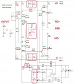
Here is a new schematic showing voltages with the +-60V rails. I let the amp play for a while and the offset on the left channel went up to 140mv. I noticed that -ND dropped from -.490V to -.330V.
One more clue. With the speakers attached, I hear a ground hum at initial switch on that fades out in about 5 seconds.
Blessings, Terry
One more clue. With the speakers attached, I hear a ground hum at initial switch on that fades out in about 5 seconds.
Blessings, Terry
Attachments
Hi Valery,
I think I have the issue resolved. I'm not sure I went about it the right way but this is what I did. I pulled the servo and hooked a 50k pot in parallel with R2. I dialled it down until I had the offset as close to zero as I could. I shut it down and measured the pot and then added a resistor of that value in parallel with R2. Restarted and read about 40mv without the servo. With the servo installed it dropped to +-5mv fairly quickly. On the right channel I installed 1k2 in R2 and R4 and that brought the VAS current down to match the left channel. Then I did the same trimmer routine as before. Now both channels match. I'm using it with the Tubsumo OPS right now. I set it at 100mA per output. It really sounds good. I haven't tried it with the Slewmaster OPS yet. I may have to drop R2 and R4 to 1k to use with the Slewmaster. I'll let you know after I try it. To anyone else planning to etch these it would be a simple thing to just draw in a little trace between pin 8 and pin7 with a sharpie before you etch.
Blessings, Terry
Last edited:
Terry, great job, nice to hear. Resistor in parallel with R2 is a good solution for balancing the offset out. There is some jfets tolerance between the channels for sure, but matching them with R2, R4 is fine. This is a cool topology, but rather sensitive to the parts' tolerances.
- Status
- This old topic is closed. If you want to reopen this topic, contact a moderator using the "Report Post" button.
- Home
- Amplifiers
- Solid State
- Cool simple "clean" CFA