I use model from Cordell and Keantoken. May be I change the name. Please use these.
thanks sir bimo.. 2 tumb for u 🙂
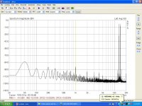
new set measurments
cfa bv modif.
Tested as mono
cfa bv modif.
Tested as mono
Attachments
-
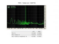 thd+noise.JPG53.9 KB · Views: 441
 -
 cfa bv steps.JPG98.4 KB · Views: 159
 -
 12v 8r.JPG118.2 KB · Views: 171
 -
 8r cfa bv.JPG112.5 KB · Views: 169
 -
 cfa bv.JPG27.8 KB · Views: 158
 -
 din rag.JPG52.9 KB · Views: 151
 -
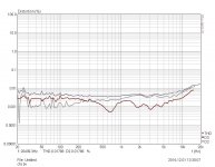
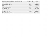
 fr res.JPG50.8 KB · Views: 397
 -
 imd swept.JPG44.9 KB · Views: 405
 -
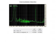 inter dis.JPG52.6 KB · Views: 413
 -
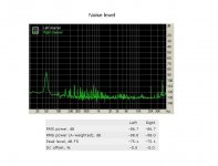 noise.JPG53.9 KB · Views: 431
Last edited:
cfa bv modif.
Tested as mono
Hi Thimios, these look very good indeed. Just 2 questions:
- Frequency response is more a sound-card's frequency response, than an amplifier's one, I believe 😉
- 50Hz (and all secondary components, like 100, 150, 200, 250, 300, 350, etc. Hz) hum - is it produced by the measurement system? I don't believe it comes from the amplifier...
Cheers,
Valery
Thanks for reply .Hi Thimios, these look very good indeed. Just 2 questions:
- Frequency response is more a sound-card's frequency response, than an amplifier's one, I believe 😉
- 50Hz (and all secondary components, like 100, 150, 200, 250, 300, 350, etc. Hz) hum - is it produced by the measurement system? I don't believe it comes from the amplifier...
Cheers,
Valery
You are right at all.
Yes 50hz isn't audible at all, it is produced by the measurement system.
Yes my sound card is old it isn't a good card but is what i have this time.
You are right at all.
I try to learn the way then maybe buy something better
What did you say for Esi Julia ?
The price is good for this,about 100e in Greece
Last edited:
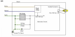
Thimios, try to disconnect direct connection from amp PSU star point to amp case (so to outlet gnd), or better replace it with 10R. Amp is during measurement connected to protective ground thru cable shield to PC protective ground, so here is masive ground loop.
I suppose , You use desktop PC with three wire AC cord.
I suppose , You use desktop PC with three wire AC cord.
2 still4given
Target of all this modifications was to improve PSRR, that is why here are cap multiplier modifications. Simply calculate time constant (RxC) of colector to base resistance and capacity from base to ground. If multiplier transistor has high enough h21, you can use larger value for resistor and so increase time constant - improving filtration. At the same time voltage drop across multiplier should remain reasonably low (2-3V), so exact values depends on transistor parameters. Here is no need to change this for other IPS in use.
This brings up a question. 470UF 100V doesn't fit the board so I have 330UF there. Should the resistors be adjusted for the 330uf? If so, what values would you suggest. I'm not sure if it matters, but I am running +-77V rails.
Thanks, Terry
This amplifier under test isn't placed in chassis yet.Thimios, try to disconnect direct connection from amp PSU star point to amp case (so to outlet gnd), or better replace it with 10R. Amp is during measurement connected to protective ground thru cable shield to PC protective ground, so here is masive ground loop.
I suppose , You use desktop PC with three wire AC cord.
I have try this with and without protective gnd connected to star gnd,i can't see any difference.
Yes i use desktop pc 3 wire outlet .
I have an issue with protective earth connector at this place.
This is an old construction with neutral and earth connected together.
Possibly that is a problem.
Thimios.
Hi Thimios,
I'm not sure if it is your case, but in my workshop I have two separate circuits and evidently they are from opposite sides of the panel. I have to be careful that all the equipment under test is plugged into the same circuit or I will get a hum. My scope is especially sensitive to this.
It is normal for the neutral to be tied to the earth ground, but only at the panel.
Hi Terry i know ,the neutral is tied to the earth ground but only inside the electrical meter.Hi Thimios,
I'm not sure if it is your case, but in my workshop I have two separate circuits and evidently they are from opposite sides of the panel. I have to be careful that all the equipment under test is plugged into the same circuit or I will get a hum. My scope is especially sensitive to this.
It is normal for the neutral to be tied to the earth ground, but only at the panel.
This amplifier under test isn't placed in chassis yet.
I have try this with and without protective gnd connected to star gnd,i can't see any difference.
Yes i use desktop pc 3 wire outlet .
I have an issue with protective earth connector at this place.
This is an old construction with neutral and earth connected together.
Possibly that is a problem.
Thimios.
If you use those ground isolation circuits that I linked to before, with the resistor/cap and bridge rectifier then it makes all of this a non issue.
A safety earth connection mind you is only really necessary when the amplifier is actually placed inside a case. It is there to prevent the chassis from killing someone should a fault develop and the chassis become live.
If the amplifier is not in a case then there's no chassis to protect someone from. If a fault develops within the amplifier circuitry itself then the fuses will blow and prevent a fire from occurring. The mains transformer typically acts as an isolation transformer and protects the user from being exposed directly to the mains. There is no harm in disconnecting the safety earth from the 'star' earth point from an amplifier that is merely sitting on a test bench. If this doesn't sit well with you, then that's fine, but if disconnecting it only for one set of measurements yields some sort of improvement then you know where a problem might lie.
If you have a wolverine board it might be worth testing the amplifiers performance with that. I have tested it and we know what it's capable of, pretty much zero distortion (that is well below 0.001% from 100Hz-10kHz) when driving an 8 ohm load when biased into class A.
I have the same issue with another amplifier which have the circuit that you say(suppose you say this ,such Rod Elliott)If you use those ground isolation circuits that I linked to before, with the resistor/cap and bridge rectifier then it makes all of this a non issue.
A safety earth connection mind you is only really necessary when the amplifier is actually placed inside a case. It is there to prevent the chassis from killing someone should a fault develop and the chassis become live.
If the amplifier is not in a case then there's no chassis to protect someone from. If a fault develops within the amplifier circuitry itself then the fuses will blow and prevent a fire from occurring. The mains transformer typically acts as an isolation transformer and protects the user from being exposed directly to the mains. There is no harm in disconnecting the safety earth from the 'star' earth point from an amplifier that is merely sitting on a test bench. If this doesn't sit well with you, then that's fine, but if disconnecting it only for one set of measurements yields some sort of improvement then you know where a problem might lie.
If you have a wolverine board it might be worth testing the amplifiers performance with that. I have tested it and we know what it's capable of, pretty much zero distortion (that is well below 0.001% from 100Hz-10kHz) when driving an 8 ohm load when biased into class A.
I know why protective gnd connected to a metal case.
I attach this star gnd to protective gnd to eliminate these issue.
I haven't built wolverine yet.
Attachments
Last edited:
I would go for it
Actually, Julia is a good one. Even used by professionals for recording / mixing / mastering. Despite the fact that it was introduced to the market 10 years ago, it is still supported by the manufacturer - drivers are Windows 7/8 compatible. It utilizes high quality AD / DA converters, so for measurement purposes - I think it would be a good choice. ASIO interface is supported. 100 euros is a good price. Make sure you've got an old-style PCI slot on your motherboard - the card was invented before PCI-e became mature.
I use e-mu 1616m (from Creative Professional) - it gives more connectivity options, however AD / DA converters in Julia are of the same high quality level, as far as I know...
By the way, for quick frequency response and phase response measurements I use Welleman's PCSGU250 appliance, combining 2-channel 12MHz oscilloscope and 1MHz function generator, providing automatic Bode Plotting functionality. Costs about 200e, connects to PC via USB 2.0 (may be used with notebook easily, providing more mobility).
See PCSGU250 spec here
Thanks for reply .
You are right at all.
Yes 50hz isn't audible at all, it is produced by the measurement system.
Yes my sound card is old it isn't a good card but is what i have this time.
You are right at all.
I try to learn the way then maybe buy something better
What did you say for Esi Julia ?
The price is good for this,about 100e in Greece
Actually, Julia is a good one. Even used by professionals for recording / mixing / mastering. Despite the fact that it was introduced to the market 10 years ago, it is still supported by the manufacturer - drivers are Windows 7/8 compatible. It utilizes high quality AD / DA converters, so for measurement purposes - I think it would be a good choice. ASIO interface is supported. 100 euros is a good price. Make sure you've got an old-style PCI slot on your motherboard - the card was invented before PCI-e became mature.
I use e-mu 1616m (from Creative Professional) - it gives more connectivity options, however AD / DA converters in Julia are of the same high quality level, as far as I know...
By the way, for quick frequency response and phase response measurements I use Welleman's PCSGU250 appliance, combining 2-channel 12MHz oscilloscope and 1MHz function generator, providing automatic Bode Plotting functionality. Costs about 200e, connects to PC via USB 2.0 (may be used with notebook easily, providing more mobility).
See PCSGU250 spec here
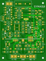
Symasui Artwork Respin
Been slow to get onto this but here is my spin on Symasui. My artwork is a fair departure from OS's but I think the design integrity remains intact.
I'm going to work towards further standardization by making this and all future redraws on 3" x 4" boards with the same mounting holes.
Been slow to get onto this but here is my spin on Symasui. My artwork is a fair departure from OS's but I think the design integrity remains intact.
I'm going to work towards further standardization by making this and all future redraws on 3" x 4" boards with the same mounting holes.
Attachments
Hey Jason,
That looks great! Looking forward to the Gerbers.
I have a couple questions about the OPS. Mine seem to have a problem with thermal runaway. Not bad but there. The drivers still run pretty hot even with a 150R in there. Is it possible that the drivers are over heating and causing the bias to rise? I have to run the bias at about 5mV per emitter to keep the heat down and then I see a ripple in the center of the sine wave that is probably crossover distortion. Almost every amp I have built has the drivers on the main heatsink. Anyway, can this be causing it? I can make larger heatsinks for the drivers but can I just keep lowering the bias on those until the issue goes away?
Thanks, Terry
PCI sound cards
Regarding the PCI interface, I like to add the following: the presence of an old-style PCI slot alone is not enough for proper functioning of your PCI sound card. You also need native support. Please see: http://www.diyaudio.com/forums/soli...ne-seen-front-end-before-108.html#post3429068
Cheers, E.
Actually, Julia is a good one. Even used by professionals for recording / mixing / mastering. Despite the fact that it was introduced to the market 10 years ago, it is still supported by the manufacturer - drivers are Windows 7/8 compatible. It utilizes high quality AD / DA converters, so for measurement purposes - I think it would be a good choice. ASIO interface is supported. 100 euros is a good price. Make sure you've got an old-style PCI slot on your motherboard - the card was invented before PCI-e became mature.
[snip]
Regarding the PCI interface, I like to add the following: the presence of an old-style PCI slot alone is not enough for proper functioning of your PCI sound card. You also need native support. Please see: http://www.diyaudio.com/forums/soli...ne-seen-front-end-before-108.html#post3429068
Cheers, E.
Hey Jason,
That looks great! Looking forward to the Gerbers.
I have a couple questions about the OPS. Mine seem to have a problem with thermal runaway. Not bad but there. The drivers still run pretty hot even with a 150R in there. Is it possible that the drivers are over heating and causing the bias to rise? I have to run the bias at about 5mV per emitter to keep the heat down and then I see a ripple in the center of the sine wave that is probably crossover distortion. Almost every amp I have built has the drivers on the main heatsink. Anyway, can this be causing it? I can make larger heatsinks for the drivers but can I just keep lowering the bias on those until the issue goes away?
Thanks, Terry
Terry,
Is it actually 'runaway' you are seeing or just the bias current shifting due to thermal lag? That is does the main heat sink temperature / quiescent current just keep rising out of control or is it just slow to track? Is it the outputs or driver that is getting out of control (or both)?
I'll have to look in the simulation but altering some of the resistor values in the bias circuit could shift a little more sensitivity to the driver temperature
sensing transistor if that ends up being the issue.
This design of OS's has a split bias circuit with one transistor tracking the drivers and another tracking the outputs. It should be pretty thermally stable. What are you using for the bias Qs? Maybe try devices with higher gain if you are using lower gain components. BD139-16 is nice for bias circuits and I have used the KSC2960AY with good success as well.
Hi Jason,
Runaway may be the wrong term. The temp just keeps rising slowly as well as the bias. It takes a while. I haven't let it run more than about an hour. the main heatsinks get really hot. Most other amps I've built, once the temp gets to a point the bias will drop a little. This never seems to happen with this one. Makes me think the thermal tracking is not working properly. I have KSC3503 in both spots. I can try BD139 in there if you think that will help. I have KSC2960AY as well. Should I use higher hFe units?
Thanks, Terry
Edmond.
I read through that entire thread and the back and forth with Waly got rather much. I assume he is rather young and has strong opinions based on strictly book information. He does seem to rely on data sheet numbers for his arguments rather than real data. If you had the option would you use a sound card like you are, The Lynx I think or something like the Audio Precision, is it costs vs performance or have you achieved equal performance with your proprietary software?
I read through that entire thread and the back and forth with Waly got rather much. I assume he is rather young and has strong opinions based on strictly book information. He does seem to rely on data sheet numbers for his arguments rather than real data. If you had the option would you use a sound card like you are, The Lynx I think or something like the Audio Precision, is it costs vs performance or have you achieved equal performance with your proprietary software?
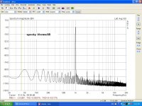
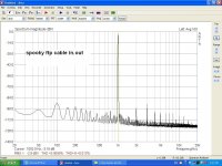
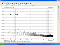
spooky
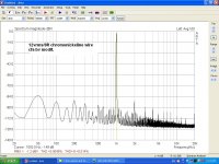
Spooky measurment
Something important between these measurements.
1st photo:results with two separate cables ,one rca to rca cable for input and another one for out .
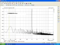
2nd photo: one ftp cable cat. 6 from which one pair worked as output from pc sound card line out and another pair as input for pc sound card line in.
Using this ftp cable, frequency around 50hz comes down -10db at least!
Spooky measurment
Something important between these measurements.
1st photo:results with two separate cables ,one rca to rca cable for input and another one for out .
2nd photo: one ftp cable cat. 6 from which one pair worked as output from pc sound card line out and another pair as input for pc sound card line in.
Using this ftp cable, frequency around 50hz comes down -10db at least!
Attachments
Last edited:
- Home
- Amplifiers
- Solid State
- Slewmaster - CFA vs. VFA "Rumble"