The same it should measure at amplifier output with and without load, too. Amp properties are better than card resolution.
Terry, look here,and read thisThe latest version has the worst looking 100kHz waves
Terry, if you want "sharper" square, you need to decrease input filter capacity (680p to some 150-220p, as in slewmaster)
The same it should measure at amplifier output with and without load, too. Amp properties are better than card resolution.
Terry, look here,and read this
http://www.diyaudio.com/forums/solid-state/248105-slewmaster-cfa-vs-vfa-rumble-59.html#post3953630
It's no big deal. It sounds just fine. Thimios must like it, he is using it for all his measurements. I just wanted to see if I could do it on these boards. Having issues gives me a chance to learn something. I'm going to try OS's mod too. Much simpler than this one. I don't have a lot of fancy measuring equipment, just my ears and an old scope.
Blessings, Terry
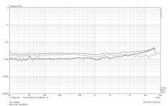
loop test 96Khz as required
Okay thimios, this gets both HD2 and HD3 about the same in level (what you'd more expect imo) and gives a good baseline for doing more measurements.
What BV was meaning is that the sound cards distortion is so 'high' that when measuring the amplifiers it should look pretty much exactly the same as the amplifiers are capable of much lower distortion.
If you get wildly different results then this is either due to bad amplifier implementation, or a problem with the measurement setup.
Thanks for all this effort.Okay thimios, this gets both HD2 and HD3 about the same in level (what you'd more expect imo) and gives a good baseline for doing more measurements.
What BV was meaning is that the sound cards distortion is so 'high' that when measuring the amplifiers it should look pretty much exactly the same as the amplifiers are capable of much lower distortion.
If you get wildly different results then this is either due to bad amplifier implementation, or a problem with the measurement setup.
I know what my soundcard is.
I don't believe that all my troubles are sound card problems.
Something is wrong with setup configuration for these measurements.
All my diy amplifiers have the same issue,finally i believe that is a ground loop problem.
Last edited:
Thimios,
I am no expert or even close to it but I have been reading a lot about ground loops on another thread. One thing I would consider if you haven't already done it is to make sure the input to the amp from the sound card has the shield at the amplifier disconnected. Some RCA cables already have one end with the shield disconnected but not in all cables. This would create one of the ground loops you are looking for,
Steven
Terry,
I have seen references to RCA cables with one end of the shield not connected. Perhaps these are only some audiophile cords that are made that way. This was one of the discussions on how to end a ground loop between a preamp and amp. cut the shield at the amp end was the solution suggested.
I have seen references to RCA cables with one end of the shield not connected. Perhaps these are only some audiophile cords that are made that way. This was one of the discussions on how to end a ground loop between a preamp and amp. cut the shield at the amp end was the solution suggested.
I tried this already but smoke comes out from amplifier.Thimios,
I am no expert or even close to it but I have been reading a lot about ground loops on another thread. One thing I would consider if you haven't already done it is to make sure the input to the amp from the sound card has the shield at the amplifier disconnected. Some RCA cables already have one end with the shield disconnected but not in all cables. This would create one of the ground loops you are looking for,
Steven

Terry look this.Terry,
I have seen references to RCA cables with one end of the shield not connected. Perhaps these are only some audiophile cords that are made that way. This was one of the discussions on how to end a ground loop between a preamp and amp. cut the shield at the amp end was the solution suggested.
But this way you can't make virtual ground
Attachments
Does anyone know what the consequences would be of trying to run the CFA-XH BV mod 2 from something like +-9 volt rails? My bench PSU only goes up to around 19 volts and I use that for most of my trouble shooting.
To compensate for this I have lowered the values of R4 and R17 down to 10k and used a 1k pot instead for trimming. I've also lowered R13 and R14 down to 2.2k.
What I'm seeing are large bias currents flowing through the output stage that I cannot reduce and decent amounts of DC offset.
I have not beta matched the input pair and cannot either as my 992/1845s are from different hFE batches. I didn't figure that this would be a problem as the hFE brackets over lap quite considerably. 300-600 for one lot and 400-800 for another. I figured I'd get some that match if I tested them, but alas, they do not vary by much. One batch are pretty much all 360 and another 480. How close a match do you need?
I am reluctant to connect the amplifier up to a beefier PSU as the bias currents are pretty large.
Well I've simulated with BVs schematic and the various transistor models provided and the thing appears to work absolutely fine on 9 volt rails with a few component changes.
I guess that means there's no point in hooking it up to the bigger supply until I get it working on the lower voltage one.
The question about the beta matching of the input pair still stands though, how close do they need to be?
I guess that means there's no point in hooking it up to the bigger supply until I get it working on the lower voltage one.
The question about the beta matching of the input pair still stands though, how close do they need to be?
+-9V PSU rails are too low for reasonable use, usable output voltage will be maybe 10Vp-p, but if you will to try it, so:
decrease R13,R17 about 10times (3k3-4k7), P1 change to 10k
R13, R14...........2k2,
R22,R23............1k5
R19..................10k-15k
And D9,D10 can be red LEDs with forward voltage at least 1.7-1.9V for all PSU voltages.
As lowest PSU voltage for "normal" use I see about +-30V (with above componets appropriate changed) .
Thimios,
always keep shield connected, it was very bad idea, "smoke" results from instability..And best solution is to omit D1,D2,R3 and connect input ground direct to power GND. But than are isolated, separated PSU for each channel needed (to avoid ground loops) ,two power transformers etc. or at least two isolated secondary windings, separated for each channel..
Last edited:
If you have a second bench PSU connect these in series. I make this every time when i do a first test to a diy amplifier.Does anyone know what the consequences would be of trying to run the CFA-XH BV mod 2 from something like +-9 volt rails? My bench PSU only goes up to around 19 volts and I use that for most of my trouble shooting.
To compensate for this I have lowered the values of R4 and R17 down to 10k and used a 1k pot instead for trimming. I've also lowered R13 and R14 down to 2.2k.
What I'm seeing are large bias currents flowing through the output stage that I cannot reduce and decent amounts of DC offset.
I have not beta matched the input pair and cannot either as my 992/1845s are from different hFE batches. I didn't figure that this would be a problem as the hFE brackets over lap quite considerably. 300-600 for one lot and 400-800 for another. I figured I'd get some that match if I tested them, but alas, they do not vary by much. One batch are pretty much all 360 and another 480. How close a match do you need?
I am reluctant to connect the amplifier up to a beefier PSU as the bias currents are pretty large.
Most of my INP haven't matched pairs except inp trans.
Thanks for all advice.+-9V PSU rails are too low for reasonable use, usable output voltage will be maybe 10Vp-p, but if you will to try it, so:
decrease R13,R17 about 10times (3k3-4k7), P1 change to 10k
R13, R14...........2k2,
R22,R23............1k5
R19..................10k-15k
And D9,D10 can be red LEDs with forward voltage at least 1.7-1.9V for all PSU voltages.
As lowest PSU voltage for "normal" use I see about +-30V (with above componets appropriate changed) .
Thimios,
always keep shield connected, it was very bad idea, "smoke" results from instability..And best solution is to omit D1,D2,R3 and connect input ground direct to power GND. But than are isolated, separated PSU for each channel needed (to avoid ground loops) ,two power transformers etc. or at least two isolated secondary windings, separated for each channel..
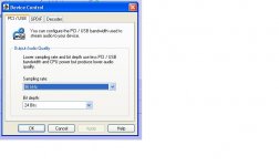
Can you post the recommended configuration diagram when ARTA software used?
Nothing special.. Loopback, signal from card output to amp, signal from amp output to card line input , via voltage divider at low impedance. Normal shielded cables, shield always connected at both sides.Can you post the recommended configuration diagram when ARTA software used?
It is good to find optimal level for card input / output for minimal distortion, and than keep signal near this level, if possible.
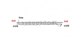
And I found basic mistake in all posted schematic here. If an input ground, isolated from power ground via 10R resistor (ground loop currents limit ) should have any sense, than grounded end of NFB resistor must be connected to this input ground (junction R2,C2,R3), not to power GND. Other way this 10R resistor only worsens mains artefacts.
For CFA amp (NFB resistor only 50R) decrease value of R3 to 1-2.2R, but best solution is not to use this resistor at all (replace with jumper to power GND).
- Home
- Amplifiers
- Solid State
- Slewmaster - CFA vs. VFA "Rumble"