Dear Damir,
don't misunderstand me. I do not want to make your amp in any way looking bad. I only want to understand the measurement differences of Richard's and my tests. Unfortunately Richard doesn't always document the environment conditions during measurements (supply voltage, bias ...).
VAS diode is meant only as an example for a blameless...
A longer feedback path isn't a problem as shown in SA2014 simulation and measurements. Of course a completely changed pcb routing can have some good/bad influence on distortion results. I will have a look on your older pcb variant and will compare this with Richards one (a link to Richards pcb version would be helpful).
BR, Toni
Hi Toni,
Unfortunately I don't have measuring equipment and can't confirm any result. My opinion, short feedback part is important. I don't remember what was ULGF of your SA2014?
Last layout is just few post back.
BR Damir
This is the one Richard used/got?...
Last layout is just few post back.
BR Damir
This is the one Richard used/got?
Very similar.
PSUs, cabling, performance of the measuring instruments ?I only want to understand the measurement differences of Richard's and my tests. Unfortunately Richard doesn't always document the environment conditions during measurements (supply voltage, bias ...).
Yes, i hope Richard will offer us a complete set of measurements with all the conditions described.
With such performances, this amp deserve-it.
Not to forget the most important: Performance/pairing of the active devices.PSUs, cabling, performance of the measuring instruments ?
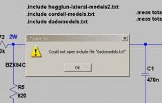
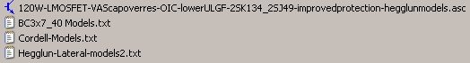
Hi dadod, for over a week ago I downloaded your .asc files packed into a zip folder for the 120W lateral FET amp, but only until now I wanted to play with it but LTspice fails to simulate because it misses the .dadomodels.txt file, I now went back in this thread to try find the original post to check if I missed something but I can't find it, what should be in the missing file?
Regards Michael
Regards Michael
Attachments
Hi dadod, for over a week ago I downloaded your .asc files packed into a zip folder for the 120W lateral FET amp, but only until now I wanted to play with it but LTspice fails to simulate because it misses the .dadomodels.txt file, I now went back in this thread to try find the original post to check if I missed something but I can't find it, what should be in the missing file?
Regards Michael
Sorry Michael, I forgot to add dadomodels.txt file, it's here now.
Damir
Attachments
This is status of the boards order:
mlloyd1 4 board shipped
AVWERK 2 board waiting for payment
trebolo 4 boards not confirmed
Lbud4 2 + 2 balancedadd waiting for payment
As trebolo did not answer my PM I have some spare boards left, so please, let me know if interested.
Damir
mlloyd1 4 board shipped
AVWERK 2 board waiting for payment
trebolo 4 boards not confirmed
Lbud4 2 + 2 balancedadd waiting for payment
As trebolo did not answer my PM I have some spare boards left, so please, let me know if interested.
Damir
200 W CFA assembling instruction
This describe how to assemble the 200W CFA and what is important to take care of.
Those transistors should be matched on Vbe, and Hfe, 5% is OK result. If matching is not so good than output offset could de higher but DC servo will take care of it.
Q11/Q12, Q3/Q4
Those transistors should be matched on Hfe.
Q33/Q34, Q14/Q2, Q6/Q8, Q5/Q/
The 15V zener diodes shoul be matched for the same voltage (D15 D16)
The LEDS D11/D12 matched for the same voltage at 2 mA.
Output MOSFETs should be matched but if bought from the same batch matching should not be the problem.
There two possibility how to configure this amp, as pure CFA with small FB board (eleven 2W resistors in parallel) or for those who bought the balanced add board the amp will become VFA with all advantage of CFA, current on demand, symmetric complementary configuration with no thump at power switch on, very stable operation good clipping behavior.
From the attached BOMs and schematics is visible how to assemble different configuration.
If the amp is going to be CFA with only non balanced non inverting input all Materials from the amp BOM is needed, but nothing from balanced add board BOM.
If the amp is going to be VFA with balanced inputs, some material is not needed from the amp BOM but all from the balanced add board BOM is needed.
I did not defined manufacturer for resistors and capacitor, just the type and you can decide if to go for more expensive components. I only suggest that you use Wishay for the output MOSFET not IRF.
To put the amp under power you should be careful. First check that the trimmer P1 is set to maximum. I use external workshop power supply with current limiter for first trial. Otherwise also good way is to use 100W incandescent lamp in series with the power supply transformer mains side.
If the VAS current stays between 4 to 8 mA (measured on VAS emitter resistor) all is probably OK, after that try to set the bias current measuring the voltage drop on the output mosfets source resistor. You can chose between 120 to 200 mA, depends how big heat sink you use.
On both schematics there are marks as +IN, MID and FB. Those points are connected together if balanced add board is used.
I hope this will help, if you need more information just ask.
Damir
Attachments
Last edited:
Some of the people who accepted the price did not pay or not answer my PMs. Here is the list, so I still have more board available if there interested, please PM me.
mlloyd1 4 board delivered
AVWERK 2 board shipped
trebolo 4 boards no answer on my PM
Lbud4 2 + 2 canceled
Damir
mlloyd1 4 board delivered
AVWERK 2 board shipped
trebolo 4 boards no answer on my PM
Lbud4 2 + 2 canceled
Damir
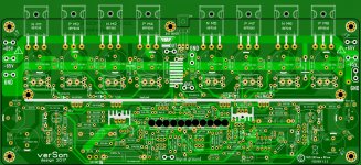
Voltage range for this board?
Hi,
The printing on the board suggest a power supply of +/-65V. This suggests a transformer of about 2x 48VAC.
When using analogue power supply, the voltage will vary a lot from loaded to almost unloaded.
What is the maximum and minimum voltage for the board?
Hi,
The printing on the board suggest a power supply of +/-65V. This suggests a transformer of about 2x 48VAC.
When using analogue power supply, the voltage will vary a lot from loaded to almost unloaded.
What is the maximum and minimum voltage for the board?
I get +-58.5Vdc from 230:dual45Vac transformer operating on 240Vac mains power.
A 230:dual45Vac on 240Vac should give around +-65.8Vac
On 230Vac a bit less, maybe +-63Vdc.
Your guess for 230:dual48Vac on 220 to 230Vac mains power is probably about right for +-65Vdc.
All mains varies.
Typically the tolerance can be as low as +-6% but I believe some generators have +-10% tolerance.
The amplifier should be assembled from components that will allow the full tolerance to be used safely.
Hi,
The printing on the board suggest a power supply of +/-65V. This suggests a transformer of about 2x 48VAC.
When using analogue power supply, the voltage will vary a lot from loaded to almost unloaded.
What is the maximum and minimum voltage for the board?
The amp will work with no problem from +-60V up to +-70V. If you want to drive low impedance loudspeakers go for lower voltage.
Damir
Thanks for the voltage suggestion.
The 2SC2240 / 2SA970 transistor pair seems hard to buy.
I assume the most important is the maximum voltage (120V in this case)?
Can use KSC1845 / KSA992 pair?
In first post there is 200W CFA assembling instruction link. Just go there and in attachment you can find Bill Of Material and there listed replacement transistors. Or go directly a few post back to post #1230.
And yes, you can use KSC1845 / KSA992.
- Home
- Amplifiers
- Solid State
- 200W MOSFET CFA amp