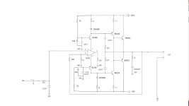
Non inverting input [schematic] does not have a dc return to ground.'Mini Quad'
Non inverting input [schematic] does not have a dc return to ground.
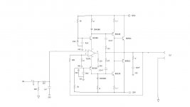
Corected
Attachments
It's shunt compensation, QUAD use another inductor but I want only one inductor in amplifier ( 16 turns on 6mm dia with 1mm wire).
Regards
The L and C are part of the feedback bridge that is the heart of the current dumping concept as designed by Quad.
The more general term 'current dumping' for an output stage in zero bias is completely different than the Quad principle.
Jan
They had an amp with a hefty driver that drove the speaker up to a watt or so, and above that, a class B stage came on.
I can understand why they would call it current dumping (if they did; don't remember).
The problem is that Qaud had christened their invention also current dumping and that is a much more sophisticated system.
In the Elektor system, you still had xover distortion. Because at the point where the class B stage came on, the system internal gain increased dramatically with a fast jump and that caused a nonlinearity (and thus distortion) in the output.
The Quad system prevented that, because as soon as the 'dumpers' came on, the system gain was automagically reduced in the same ratio leading to an almost complete absence of xover distortion.
Jan
I think we might be thinking of different amps Jan. The one I remember really was just a 741 and darlington outputs. It was very very basic but described I think as 100watts into 4 ? ohm. It was just a "summer circuit" one.
I remember the name "Edwin" amp and turned this up,
http://www.diyaudio.com/forums/solid-state/165165-edwin-20-watt-elektor-1970-may.html
I remember the name "Edwin" amp and turned this up,
http://www.diyaudio.com/forums/solid-state/165165-edwin-20-watt-elektor-1970-may.html
Its a small class A being rescued by a class B - isn't that what was the subject of 'current dumping' here?
Jan
It seems so, yes.
explanations
to be clear:
small class a are: BC546/556,
big class b are: bd140bd911/bd139bd912?
It seems so, yes.
to be clear:
small class a are: BC546/556,
big class b are: bd140bd911/bd139bd912?
I remember the Elector amp, it used a similar topology to the one in post 21, using the opamp to drive a load and the supply currents to drive the output transistors. I built one for use in the car along with an inverter to generate -12V, this would have been about 1980, from what I remember it worked quite well. I also built a few 405 clones
Stuart
Stuart
Why is the output of the driving opamp not connected to the amplifier output..?? (the mini Quad)
OP amp output is connect to load resistor 220R, and voltage drop on 51R resistors drive BD139/140. 51R, 5R1 with 1N4148 made current multiplayer X10 for drivers. BC546/556 is only cascode transistors, OP amp drive BD139/140.
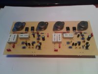
Some new build
The layout is different from the one I made earlier. Can we see how the pcb design was done?
pic in post10.
The aluminium (or copper) angle transferring heat from the To3s to the sink should be optimised for excellent thermal performance, i.e. coolest To3 Tc.
Make the angle longer than the PCB width. Try 120mm to 150mm long.
Make the angle thick. Try 5mm to 7mm thick.
Keep the To3 as close to the heatsink as possible:
a.) omit the "gap" between the To3 case and the angle. Saw one edge/side of the angle to minimise this gap. Or use an unequal angle (not commonly available)
b.) turn the "angle" upside down, to allow the To3 case to come closer to the sink.
Use Thermal paste between the angle and the sink.
Use many bolts/screws to clamp the angle in very close contact with the sink. Aim for at least 6 clamping points, one up & one down at each side of each To3. Two rows of 5 fixings would be better.
I know it's been a while since we were working on this one, but better late than never
")
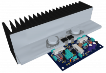
Here is something that's mostly in line with better heatsinking.
Attached is a new rendering with a conrad heatsink MF20-1F-75, which has a better thermal resistance of 0.6C/W:
Conrad Heatsinks - Products
This should dissipate more than that previous one from fischer (SK155) that was 150mm wide and I had chosen a length of 120mm, which should've yielded something around 0.75C/W of thermal resistance.
http://www.fischerelektronik.de/web_fischer/en_GB/heatsinks/A01/Standard%20extruded%20heatsinks/PR/SK155_/$productCard/dimensionParameters/index.xhtml
It seems this amp creates quite a bit of heat, so it requires a serious sink to match.
I picked the 200mm long version from conrad, as the shorter 150mm although it would've been just right for the pcb, would have yielded only 0.78C/W.
Still, this 200mm long sink isn't really that big, and because of its built-in flange, this avoids the extra aluminum corner and its associated extra thermal junction.
This should work much better, and just in case, there is also an even longer 300m version if it turns out this one isn't quite enough (for 4ohms load perhaps).
And lastly, there is even more to do eventually, since the pcb has 30mm for the TO3s and the conrad sink's flange is 35mm, the extra 5mm of flange could be shaved off, or a notch for the pcb could be made, so the TO3s would be almost against the main sink.
Far more efficient already
Attachments
- Status
- This old topic is closed. If you want to reopen this topic, contact a moderator using the "Report Post" button.
- Home
- Amplifiers
- Solid State
- Current Dumping Amplifier