If you can hear anything up in that range, you do not need a receiver to listen to radio....Hi Pete.
Can you trace the HF limit without the input RF suppression cap installed? Or maybe with, say, 10pF in place of it (15MHz limit)? Will be great to know.
Thanx.

Unfortunately not. My poor Signal Generator goes to 4MHz maximum, and above 1MHz (1-4Mhz scale) already starts to become inaccurate.
Glass diodes, really? Please explain...

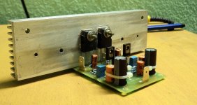
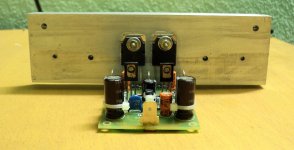
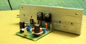
@ Bonsai: Thanks, that is actually my modular test/prototype chassis. Not finished, sadly. Clear satin anodized heatsinks, front and back panel thermally coupled. Stainless base and top.
Looks nice no thanks to me, (chuckle). Built by a friend in a local machine shop. I am trying to turn it into something to use both for VSSA, and nx-Amp (bit bigger for nx-Amp)
Play time is over here, bedtime beckons...
")
If you can hear anything up in that range, you do not need a receiver to listen to radio....
Unfortunately not. My poor Signal Generator goes to 4MHz maximum, and above 1MHz (1-4Mhz scale) already starts to become inaccurate.
Okay. Understood.
Glass diodes, really? Please explain...
The 1N4148s, biasing the FETs pretty well near ideal Iq and keeping the bias voltage constant even if VAS current fluctuates a lot. Reason to eliminate resistive bias spreader.
shaan
Mr. Shaan or jr. I would love to make my own pcb,s but my hands are in such a state of uselessness that it would be a joke to even try. Evette
Sorry, Evette, I could't know.
Regards
I am very tempted to cancel my order for the LC VSSA modules and build this instead. This feels a lot more like DIY than plugging modules together. Besides, those Alfets are looking more and more like unobtainium.
I still have a couple bottles of etching solution around here somewhere.
I still have a couple bottles of etching solution around here somewhere.
still4given,
This version is definitely worth a try, whichever flavour you choose. I love mine, they are the nicest sounding amps I've used to date. Very straight forward DIY and no unobtanium required. In fact, they are pretty forgiving of parts choices. I have enough outputs left (mine is the TO-3 version BTW) for six more channels and I'd like to make my next set with some better components to see if there is any real difference.
I DO have a stereo set of LC's VSSA boards that I have not yet tried as I'd like to get a set of SMPS supplies for those, so can't say comparatively speaking what they are like.
I cancelled my order. I enjoy the build too much to buy modules. I have plenty of great sounding amps. That is not my quest. I want to learn and the more designs I build, the more trouble shooting I seem to do and the better grasp I get on how things work together. I will probably build one of these as soon as Pete finishes his new version.
I just finished a JLH using a servo power supply. It's burning in right now.
I still have a set of Honey Badger boards to build and a set of DX Blame MXIII on the way.
Fun stuff!
I just finished a JLH using a servo power supply. It's burning in right now.

I still have a set of Honey Badger boards to build and a set of DX Blame MXIII on the way.
Fun stuff!
Hi still4given. 
Welcome to the PeeCeeBee thread.
Please don't if possible. As I'm pretty sure LC's little wizards will play magic on your speaker.
How about building this before buying LC's cards. Like trying a demo before installing the full-version.
It can certainly give you a clear hint of the sound of a well-designed six transistor Class-AB symmetrical CFB amp and how good might the best of them be, for a few dollars or less if you already have some of the parts. You can save the bigger part of the budget for the modules.
Yes. Only pure DIY here.
cheers
shaan
Welcome to the PeeCeeBee thread.
I am very tempted to cancel my order for the LC VSSA modules.
Please don't if possible. As I'm pretty sure LC's little wizards will play magic on your speaker.
and build this instead.
How about building this before buying LC's cards. Like trying a demo before installing the full-version.
It can certainly give you a clear hint of the sound of a well-designed six transistor Class-AB symmetrical CFB amp and how good might the best of them be, for a few dollars or less if you already have some of the parts. You can save the bigger part of the budget for the modules.
This feels a lot more like DIY...
Yes. Only pure DIY here.
cheers
shaan
I want to learn and the more designs I build, the more trouble shooting I seem to do and the better grasp I get on how things work together.

Shaan, this is my newest one...
I will try it, any suggestion ...
& power resistor added
all elco up to 20mm diameter, 18mm at now
I want to be the first one try the 2 OP pairs
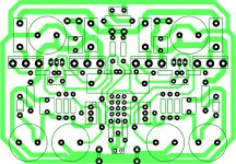
it is not final layout yet
Nice trick for bc and sa/sc input pair accommodation.
Looks like the second of the three resistors near the right trimmer is missing a connection.
I cancelled my order. I enjoy the build too much to buy modules. I have plenty of great sounding amps. That is not my quest. I want to learn and the more designs I build, the more trouble shooting I seem to do and the better grasp I get on how things work together. I will probably build one of these as soon as Pete finishes his new version.
I just finished a JLH using a servo power supply. It's burning in right now.
I still have a set of Honey Badger boards to build and a set of DX Blame MXIII on the way.
Fun stuff!
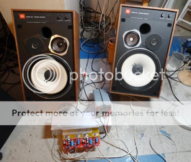
Terry,
Is that good old JBL 4311 or 4312? Great loudspeakers (Alnico magnets!). They don't make it like that anymore. People can't believe how close is voice coil to the magnet gap. Precision assembly!
BTW, I decided to replace too high value current feeder resistor (22k) with optimal value for my psu voltage (18k) and to make front end current higher, meaning correct. The sound is now much better, cleaner, crisper and more detailed. Too low front end current is definite no-no.
Last edited:
...to make front end current higher, meaning correct. The sound is now much better, cleaner, crisper and more detailed. Too low front end current is definite no-no.
As I mentioned in an earlier post, I decreased input collector load resistors from 470R to 220R and current injectors from 12K to 5K6 [+-28V PS] resulting into about 4.8mA input current, like the SSA of last year.
VAS current is about 20mA.Well, I've been listening to the modified version everyday since then, everyday for at least 2 hours and more than 10 hours for 2 or three days. The sonics are apparently much more close to what I call 'natural'. The overall midrange and drum-strokes are now like the real things, real, 'close your eyes and see'.
Lows and highs seem unaffected, same extra-ordinary I mean.
Will stick to this config.

p.s. The feedback caps were 'set-in' for 24 hours or so with 3V battery before any assembly so I'm sure they aren't adding their own 'story' into the signal.
Terry,
Is that good old JBL 4311 or 4312? Great loudspeakers (Alnico magnets!). They don't make it like that anymore. People can't believe how close is voice coil to the magnet gap. Precision assembly!
BTW, I decided to replace too high value current feeder resistor (22k) with optimal value for my psu voltage (18k) and to make front end current higher, meaning correct. The sound is now much better, cleaner, crisper and more detailed. Too low front end current is definite no-no.
Yes, 4312. Don't be mad at me but those are my "test speakers". They have had a rough life. Given to me because one of the woofers had a big tear in it as well as one of the midrange speakers which was torn and had a damaged dome cover. I was going to recone them but instead I have just glued the tears and removed the damaged dust cover. They actually sound very nice. Because I have no investment I figure to use them for test speakers and if they get hurt then I will go about reconing them. I have two pair of 4412s and a pair of 4425s as well. I am kind of enjoying the 4312s as they are a little less detailed and therefore more forgiving.
Looking forward to building the VSSA. Should be able to get started on it in a few weeks.
Blessings, Terry
Last edited:
Hi Ivan,How high is the output stage current without 470R resistor (with only a pair of 1N4148 diodes)?
tell us your rails?
On mine there was about 200mA total current (when I add 10 ohm resistor at rail = 200mV on it)
and when the rail is at +/-33VDC
with or without 470R resistor is not much different in my case.
Different rail give you different current, maybe Shaan can help us to stabilize it
Last edited:
Hi Terry,
do you want to try this one?
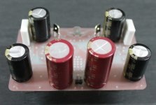
this is it my newest PeeCeeBee
I will do it slowly
Wow .. nice build Bli John,
Are those red elcos is elna cerafine?
Hi Ivan,
tell us your rails?
On mine there was about 200mA total current (when I add 10 ohm resistor at rail = 200mV on it)
and when the rail is at +/-33VDC
with or without 470R resistor is not much different in my case.
Different rail give you different current, maybe Shaan can help us to stabilize it
My rails are 38V, but I am interested how much difference the resistor makes in general. I do not want to desolder resistor just to measure the difference.
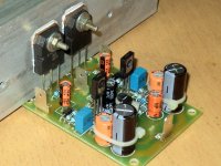
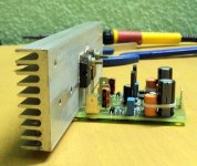
Now cooking -
This baby is going to drive my 50W DIY spherical sub. The heatsink is a bit small... but will be fan cooled.
This baby is going to drive my 50W DIY spherical sub. The heatsink is a bit small... but will be fan cooled.
Attachments
On mine there was about 200mA total current (when I add 10 ohm resistor at rail = 200mV on it)
Hi John.
200mV on 10R will indicate 20mA instead of 200mA. Is the resistor really a 10R or 1R? Or is the meter showing a dot in the reading? Like '20.0'.
The bias won't vary considerably with different PS voltage If the diodes are used in the biasing node. The story will be different with purely resistive bias whose bias voltage depends directly on VAS bias current, meaning FET bias will be significantly dependent on VAS bias, which ideally should not be allowed.
shaan
- Home
- Amplifiers
- Solid State
- PeeCeeBee