thanks a lot jkuetemann, you encourage me to built this amps.Check out the thread here, despite its title the thread has produced various configurations including BJT options for outputs. It is based on the same basic structure as the original VSSA and PeeCeeBeee.
I ordered mine from Tayda Electronics@shaan, Good day, is it possible to change FET to a transistor(C5200/A1943)? It's hard to find FET in my location. Thanks..
https://www.taydaelectronics.com/catalogsearch/result/?q=2sk10
https://www.taydaelectronics.com/catalogsearch/result/?q=2sj162
Hi Masood...dear what secret formula
Use BD139-140 instead any higher speed transistor so no need any compensation caps.
The speakers just for funAgh... what innovative speaker design John!
Congrats. You are the first to build the dual FET PeeCeeBee made of edible sweet solids.
Please upload the pdfs of layout, silkscreen and mask if you think we should eat... uuh.. build it too.
Again, what innovative speakers John, quite inventional haha...


 has build it long time ago
So here the PDF but no value cos I don't have it
please send me PM if someone want the .dip file(I use diptrace)
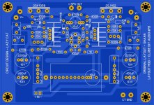
board size : 100mm x 64mm
I need someone that build it too
Attachments

Last edited:
@shaan, Good day, is it possible to change FET to a transistor(C5200/A1943)? It's hard to find FET in my location. Thanks..
Hi wenz.

I think it is possible.
With CFP/Sziklai outputs the amp should produce good sound [with some extra care to prevent oscillation in the o/p stage].
All the best.
shaan
Wow, but I cannot order it since my location is far from the city. II will try first using transistor that i mention above, if failed, then proceed to the original parts.I ordered mine from Tayda Electronics
https://www.taydaelectronics.com/catalogsearch/result/?q=2sk10
https://www.taydaelectronics.com/catalogsearch/result/?q=2sj162
I already have a DIY amps, all are TEF, I did not try CFP/Sziklai outputs,Hi wenz.
I think it is possible.
With CFP/Sziklai outputs the amp should produce good sound [with some extra care to prevent oscillation in the o/p stage].
All the best.
shaan
maybe I will have to try CFP/Sziklai and modify it to TEF if CFP is working.

...I will try first using transistor that i mention above, if failed, then proceed to the original parts...
I hope none of your PeeCeeBee experiments fails.
cheers...
sorry for that... but the PDF is fine...Hi John.
Can you please repair the horizontal stripes in the layout?
Thanks.
here the corrected one (I'm not familiar with the "pdf/image printer" software
)Attachments

last version
Here the latest version, some tweaks and fixes. The spaces are great for those who want to use polypropylene capacitors, but can also be used small electrolytic capacitors.
Sorry if it's posted in the wrong location, please enter the correct location
Thanks.
Here the latest version, some tweaks and fixes. The spaces are great for those who want to use polypropylene capacitors, but can also be used small electrolytic capacitors.
Sorry if it's posted in the wrong location, please enter the correct location
Thanks.
Attachments
Hi efragnani.
Nice design.
If you want to use this thread for posting your progress then please don't post any layout with parallel capacitors in feedback network/resistive bias/CCS in the circuit. You can modify the rest of the circuit in any way you want.
Please read the first post thoroughly, specially the 'Important' marked paragraph, before posting future designs.
Thankfully
shaan
Looking at the several threads on this design, I am amazed and a little confused.
I am looking to see if I can build one of the many designs, I would like to use +/- 18V with some BJT as outputs TO-247 type.
Is there a single sided board layout for this? I hope so.
Thanks to ALL for all for the considerable work.
I am looking to see if I can build one of the many designs, I would like to use +/- 18V with some BJT as outputs TO-247 type.
Is there a single sided board layout for this? I hope so.
Thanks to ALL for all for the considerable work.
Thanks Shaan! I already intend to read the rules and follow them, sorry for the inconvenience.
Anyway, we'll keep reading this topic.
Hi efragnani.
You are most welcome.
Please do post your PeeCeeBee progress report.
Thank you.
Looking at the several threads on this design, I am amazed and a little confused.
I am looking to see if I can build one of the many designs, I would like to use +/- 18V with some BJT as outputs TO-247 type.
Is there a single sided board layout for this? I hope so.
Thanks to ALL for all for the considerable work.
Hi Krisfr.
This thread focuses on the simplest six-transistor-only VSSA schematic and amps build on it. Using BJTs as output devices IMO is no problem, but you will need 1. drivers for the power devices and 2. a Vbe multiplier in the bias node. So it will become a 9 transistor circuit.
I think you will get sure help from the friends in the FET-HEX-EXPLENDIT thread. They are discussing, designing layouts and building full BJT VSSA in the thread. I hope there you find a suitable layout for yourself soon.
cheers
shaan
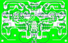
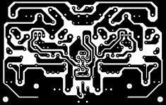
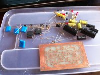
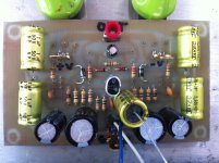
PeeCeeBee ala John Bali style
Built PeeCeeBee using John Bali PCB layout.
Parts used:
BC547B/BC557B because BC560C was not available (I think this product was discontinued and replaced by BC556C?)
all 1uF caps, input cap were all non-polar caps (JakeC brand)
all resistors were regular carbon resistors
rail DC was +/-25V.
first on, i burned 10R resistor while the other 10R became 6.6R found the problem. cause was swapped input transistors.
second on, output DC was somewhat unstable, so i put VAS compensation caps of 24pF.
third on, offset DC was high at 82mV. i tried to parallel 15k with 150k, offset DC became -82mV. i tried another value 330k, and the offset was 2 mV.
satisfied with above and was pretty stable.
sound was clean and loud. i liked the bass, mid, and high and suited my taste.
Built PeeCeeBee using John Bali PCB layout.
Parts used:
BC547B/BC557B because BC560C was not available (I think this product was discontinued and replaced by BC556C?)
all 1uF caps, input cap were all non-polar caps (JakeC brand)
all resistors were regular carbon resistors
rail DC was +/-25V.
first on, i burned 10R resistor while the other 10R became 6.6R
found the problem. cause was swapped input transistors.second on, output DC was somewhat unstable, so i put VAS compensation caps of 24pF.
third on, offset DC was high at 82mV. i tried to parallel 15k with 150k, offset DC became -82mV. i tried another value 330k, and the offset was 2 mV.
satisfied with above and was pretty stable.
sound was clean and loud. i liked the bass, mid, and high and suited my taste.
Attachments
Built PeeCeeBee using John Bali PCB layout.....satisfied with above and was pretty stable......sound was clean and loud. i liked the bass, mid, and high and suited my taste.
Hi jaagut.
Congrats! Nice build.
We will be delighted to have a detailed review on the sonics of your boards. Especially because carbon resistors are used throughout the board and low noise input transistors weren't used. How good the soundstage is with a stereo setup is one of the most important points and also the reason why one amp sounds better than another. Have you compared its sound with other amps yet? What do you feel different/better or different/worse(if any) with PeeCeeBee?
Sorry for so many Qs.
Please give it a good week-long listen and kindly report afterwards.
Thanks.
shaan
Perhaps someone can review the availability of parts and the pros and cons, with regard to what is available in the dozen different countries represented here. I think I just keep assuming that if one has access to the internet, parts can easily be ordered, but I have come to realize that shipping costs and other obstacles can be ridiculous for what should be some 10-cent parts...
I think I am starting to appreciate this more with my recent experiences (nx-Amp, where I have so far paid more for shipping than the cost of a couple sets of parts ... ) Incidentally, nx-Amp uses BC547C/BC557C in the input, with BC546C/BC556C as higher voltage alternatives.
In the case of PeeCeeBee (my first version built according to Shaan's schematic, and incidentally the one I listen to most often), I procured the power transistors from Tayda Electronics for $4.99 each, plus modest shipping.
Most of the rest of my parts came from Mouser, and are also available from Newark (Farnell).
@ Shaan: as far as I can tell, the main source of noise that I can see on my venerable Tektronix 'scope is the power supply, and second, EMI coupled from the inexpensive toroidal transformer I am using in my test setup, and its leads. This can be seen by comparing the output when using my bench supply.
The most sensitive point is the twisted pair connection from the back panel to the input terminal on the board. This can be seen on the scope, by moving the input leads back and forth by hand - closer to the transformer, the noise on the output grows. Further away, it shrinks.
I think I am starting to appreciate this more with my recent experiences (nx-Amp, where I have so far paid more for shipping than the cost of a couple sets of parts ...
) Incidentally, nx-Amp uses BC547C/BC557C in the input, with BC546C/BC556C as higher voltage alternatives.In the case of PeeCeeBee (my first version built according to Shaan's schematic, and incidentally the one I listen to most often), I procured the power transistors from Tayda Electronics for $4.99 each, plus modest shipping.
Most of the rest of my parts came from Mouser, and are also available from Newark (Farnell).
@ Shaan: as far as I can tell, the main source of noise that I can see on my venerable Tektronix 'scope is the power supply, and second, EMI coupled from the inexpensive toroidal transformer I am using in my test setup, and its leads. This can be seen by comparing the output when using my bench supply.
The most sensitive point is the twisted pair connection from the back panel to the input terminal on the board. This can be seen on the scope, by moving the input leads back and forth by hand - closer to the transformer, the noise on the output grows. Further away, it shrinks.

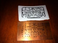
Yeah, some of the layouts here should be framed... definitely more like art than like science!Lookin' at jaagut's bare board makes me think... one can't get more DIY than this...
(I often think that posting facts and numbers here just spoils the good mood)
- Home
- Amplifiers
- Solid State
- PeeCeeBee