Certainly agree about the total system distortion ...!! Every step adds its own litte bit - I suspect having too many different types, characters of distortion is more important than the total amount, as far as one's hearing goes. Trying to sort out all the different distortion signatures, unconsciously, while listening becomes stressful - multiplies the fatiguing factor ...
With regard to the 8K frequency, just recently did a little experiment, for other reasons, of digitally chopping off all frequencies above a certain point, on a dense pop mix with lots of treble content. This was on simple PC speakers, which still can produce an audible 18kHz tone.
Using only casual listening, it was obvious that a lot was lost if the cutoff was 8kHz; 10kHz it became more subtle, but by 12kHz it was all but undistinguishable from the original. Only with very, very careful listening, which I didn't try, would I have been able to pick the variation ...
I am referring to 8KHz in music content. but, you are right about the 12Khz point. In fact, the BBC did similar studies and came to same conclusion -- their BBC monitor need not go beyond 12kHz.
Now there are plenty of others who have done studies from a different angle and determined higher freqs were important and lent a different character to the sound.
So for a high-end design you might need to use the best/worse case numbers and try for them..... they wont always be needed but this is for the Highest of Hi End performance. Take no prisoner level. Use the widest range and the lowest number to be sure everyone, under any condition -- even a fluke combination of errors will not be audible. Very Low, very high, very wide, etc. Perfection.
It really, truely has to be looked at as a system including all the interfacing, emi/rfi issues.
Hey! If it was easy we would have music that sounds like real music being played in our listening room a long time ago... instead of nice hi-fi sound.
Thx-RNMarsh
Last edited:
To try and get to the heart of the matter I looked up some material from Analog Devices, who might just know a thing or two about such things,. Jung's "Op Amp Applications Handbook"
I was looking at the very same outstandingly useful body of work myself - available in bite-sized chunks here : ADI - Analog Dialogue | Op Amp Applications Handbook
Since the discussion has polarized into CFA vs VFA part6 of the above also introduces applications of the AFA which subjectively I find gives excellent results despite being more akin to VFB than CFB.
Part of the problem, as I see it, is that the sound often gets subjectively worse as you approach peak quality - it's only because I've been there many times that I know that I have to 'punch' through that psychological barrier, keep persisting in applying all the tweaks until the SQ breaks through into the 'clean' space - this is particularly so with digital replay .
Others may have tried various procedures, and to their ears the quality was getting worse: more aggressive, shrill, overdone. So they back off, go the "nicer" way - which is pleasant enough, but will rarely lead to the improvements which is real progress ...
Others may have tried various procedures, and to their ears the quality was getting worse: more aggressive, shrill, overdone. So they back off, go the "nicer" way - which is pleasant enough, but will rarely lead to the improvements which is real progress ...
Last edited:
Using only casual listening, it was obvious that a lot was lost if the cutoff was 8kHz; 10kHz it became more subtle, but by 12kHz it was all but undistinguishable from the original. Only with very, very careful listening, which I didn't try, would I have been able to pick the variation ...
12k+ "undistinguishable " ??
I tried this (with an open mind - and a pc ).
David Gilmour - 320Kbs CBR mp3's .... the test source.
At 8k/10K = hi-fi ....ha ha
At 12k = I could tell , easily .. sounded like a lower quality 128-192kbs mp3 , a shallow sound field.
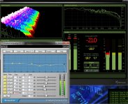
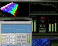
At 15K , I created a low pass preset so I could switch in/out all (most) 15-20k info ..
(below). I could see your point there , but at high volumes with a 100W amp
the 15K+ info was still readily noticeable , the placement of especially cymbals/bells/brushes. The 320K bitrate's improvement DOES exist.
I never tried this , but could always see the lack of 15k+ info in 192kbs material.
I really had to "crank it up" to hear the 15-20k content. No clicks or gaps , I even automated it so I didn't have to move at all. It's there and it counts !
OS
Attachments
Hmmm, looks like your filter is not truly "brickwall", so knee frequency slope and phase shifts could play a part here. I was using an 8191 tap, the maximum, filter in Audacity which means the cutoff is like a, well, brickwall: 0 to -120dB in close enough to a vertical line drop off ...

I still feel my VAS dangling from my chin, thanks Bonsai
The nice thing about a group hug is that it can also be like a rugby scrum: A quick uppercut and no one can prove who did it.
To try and get to the heart of the matter I looked up some material from Analog Devices, who might just know a thing or two about such things,
Seems pretty straighforward to me ...The CFB topology is primarily used where the ultimate in high speed and low distortion is required. The fundamental concept is based on the fact that in bipolar transistor circuits currents can be switched faster than voltages, all other things being equal.
Not really. The last sentence is factually incorrect. So-called "CFAs" slew faster than classic VFAs because their input stages operate in class-AB. Not that this is not necessarily the case with all so-called "CFAs".
Otherwise, all so-called "CFAs" operate just like VFAs, with the exception of the fact that in so-called "CFAs" the feedback network affects the forward path of the amplifier. Thus the assertion that so-called "CFAs" are founded "...on the fact that in bipolar transistor circuits currents can be switched faster than voltages..." is arrant rubbish.
Mikeks wrote 'Not really. The last sentence is factually incorrect. So-called "CFAs" slew faster than classic VFAs because their input stages operate in class-AB. Not that this is not necessarily the case with all so-called "CFAs".'

Wrong.
You really must check your facts here Michael before making blanket statements.
IC CFA's I believe do this on some designs for power saving ('current on demand') but I am open to correction on that.
In a discrete design, fully class A front end in CFA is easily done by design and can be made to handle over and beyond the maximum expected input signal. Please take a look at the sx & nx designs: the input stages do not go anywhere near class AB and remain firmly in the class A region.
Last edited:
Mikeks wrote 'Otherwise, all so-called "CFAs" operate just like VFAs, with the exception of the fact that in so-called "CFAs" the feedback network affects the forward path of the amplifier. Thus the assertion that so-called "CFAs" are founded "...on the fact that in bipolar transistor circuits currents can be switched faster than voltages..." is arrant rubbish.'
I think you're just trying to be contentious here, as always, Michael!
At a technical level you've missed the boat (and please don't throw that shunt/series stuff out there again, since we've heard it before).
Secondly, if what you are saying is correct, WJ and the rest of his colleagues operated completely independently from each other and basically published and perpetuated a load of garbage about CFA. I find that an extraordinarily tenuous proposition. In other words its a nonsense.
However, arrant is a nice new word I learnt today, and for that I thank you.
Last edited:
Mikeks wrote 'Not really. The last sentence is factually incorrect. So-called "CFAs" slew faster than classic VFAs because their input stages operate in class-AB. Not that this is not necessarily the case with all so-called "CFAs".'
Wrong.
You really must check your facts here Michael before making blanket statements.
IC CFA's do this on some designs for power saving ('current on demand').
In a discrete design, fully class A is easily done by design over and beyond the maximum expected input signal. Please take a look at the sx & nx designs: the input stages do not go anywhere near class AB and remain firmly in the class A region.
Actualy wanabee CFA amps do not really slew faster than VFAs ,
that s a common misconception that arise from the generic designs
properties that do not pay much attention to slew rate once an adequate
minimal value is reached.
IIRC i already pointed that with high Ft devices , 5ghz , differences
in speed between VFAs and CFAs become insignificant.
Below are the rising times of Gaborbela s old amp , popularized by Lazycat
in his variants compared to a symmetrical differential that has the same
standing currents for the IPS and VAS , with both topologies using
the same 5ghz Ft transistors.
Attachments
Don't it was clear i told about input capacitances of the (base and emitter) input transistor ?
I suppose you know the charge (and discharge) curve of a capacitor ? (i'm too able to be supposing and arrogant)
What is the difference, at a given frequency, between a phase difference and a delay ? How can-you tell looking at the two waves in an oscilloscope ?
Unless you have a flat bandwidth in open loop, you will have phase turns at the upper frequencies between original signal and feedback signal.
They will act like a delay (increasing with frequency) between error and correction. As the amplifier is not perfect, this will increase high order distortions.
The real meaning of this delay is not clear at all.
Is it a propagation delay ?
Of course, there is the speed of the propagation of current : around 3 000 000 000 m/s.
For 10 cm, which could be the typical length of the path for the signal this represents 33 pS.
There is also the existence of time transits in bipolar transistors. I do not have data about them.
However, I still have to meet somebody having taken these transit times in account in an audio circuit. Anyway, they should be about the same in VFAs or so-called CFAs : insignificant.
Trying to estimate delays in feedback loops
In audio amps, I've only seen Neslon Pass mentionning a delay for his Treshold products : loop propagation time (propagation delay appearing at the bases of the input differential transistors)
400 A : 20 nS
800 A : 40 nS
In 2009, I submitted a Blameless amp, and TL072 and LM1458 op-amps set for unity gain to square waves having 20 nS rise time and compared the input and output of the circuits with a dual trace oscilloscope.
I found the following time differences between of the "foot" of the input square signal and the emergence from noise of the corresponding signal :
Blameless : 50 nS (30 µV/µS)
TL072 : 80 nS (11 µV/µS)
LM1458 : 180 nS (0.5 V/µS)
The found values seems to be related to the noise treshold than anything else.
Effet of pure delay in feedback
Simulation can easily show the behaviour of the substraction to a signal
of the same signal submitted to a phase delay and to a pure delay.
Those who think there is pure delay in feedback should investigate...
Is it group delay ?
If the open loop amp frequency response can be assimilated to a first order low
pass filter, and the delay assimilated to the calculated group delay of this
filter :
for a low pass at 100 Hz (-3.01 dB)
at 100 Hz, phase lag 45°, group delay 791 µS
at 1000 Hz, phase lag is 84°, group delay is 15.7 µS
at 10000 Hz, phase lag 89°, group delay 156 nS
For a low pass at 10000 Hz (-3.01 dB)
at 1000 Hz, phase lag 5.71°, group delay 15.7 µS
at 10000 Hz, phase lag 45°, group delay 7.91 µS
at 100000 Hz, phase lag 84° group delay is 156 nS
Above 1000 Hz, the group delay is smaller for the 100 Hz low pass filter
than for the 10000 Hz low pass filter ! This contradicts :
Unless you have a flat bandwidth in open loop, you will have phase turns at the upper frequencies between original signal and feedback signal. They will act like a delay (increasing with frequency) between error and correction.
Slew-rate
The slew-rate specification of an amplifying circuit is a short to express the maximal value of slew the circuit is able to attain. Are audio signals which have limited rise-times better handled by fast amplifiers ?
To put this in numbers, for an amplifier of 100 W (40 Vpk / 8 Ohm) outputing a signal of 5 V/ µS (40 Vpk at 20 kHz, which is much more than the maximum audio signals it will ever encounter), are there any detectable difference if if it has a maximal slew-rate of 25 V/µS, 200 V/µS or 1000 V/µS ?
Just a reminder of real maximal voltages involved in home sound reproduction :
diyAudio - View Poll Results
My conclusion
I think using CFB or input diamond circuits is sometimes justified for a better control of the phase control at very high frequencies needed for some circuits. For instance :
- the Quad Dumping amplifier uses CFB with a single transistor input,
- the Pax amp uses an integrated circuit with an input diamond circuit in its error correction loop.
CFAs can certainly be made to work properly but I do not see in which aeras they could be qualified as superior to VFAs.
However, being curious, I always keep an eye on proposed CFAs.
The real meaning of this delay is not clear at all.
I would only add that audio circuits minimize the group delays, since minimum phase systems have minimum group delays. Also, the group delay audibility is in the milliseconds range (important for speakers, rather than for amplifiers), see here, so any claim about a group delay impact in audio electronics are purely speculations.
I think you also missed one of the most important properties of CFAs: for a given ULGF and loop gain, they can be always made unconditionally stable. This is usually impossible for VFAs with high loop gain, the phase always dips significantly before the ULGF.
Otherwise, teaching a horse to sing is a waste of time, and it annoys the horse.
Mikeks wrote 'Not really. The last sentence is factually incorrect. So-called "CFAs" slew faster than classic VFAs because their input stages operate in class-AB. Not that this is not necessarily the case with all so-called "CFAs".'
Wrong.
You really must check your facts here Michael before making blanket statements.
IC CFA's I believe do this on some designs for power saving ('current on demand') but I am open to correction on that.
In a discrete design, fully class A front end in CFA is easily done by design and can be made to handle over and beyond the maximum expected input signal. Please take a look at the sx & nx designs: the input stages do not go anywhere near class AB and remain firmly in the class A region.
A so-called "CFA" input stage (those which are complementary push-pull) will operate in Class-A until the current demanded by the shunt compensation capacitor exceeds the quiescent current of the stage.
This occurs, for example, when rapid voltage changes across the compensation capacitor are demanded of the stage's output at sufficiently high frequencies. The input stage then reverts to Class B operation to supply the demanded current.
It is bad enough that Class-AB operation is tolerated in the output stage; extending it to the front end of the amplifier is near perverse.
Last edited:
By the way, Forr, the articles that Douglas Self should have given reference to when he wrote the section on the importance of current mirrors for the input stage in his papers and books are given below:
1. Taylor, E. F., ‘Distortion in Low-noise Amplifiers: 1’, Wireless World, August 1977, pg. 28.
2. Taylor, E. F., ‘Distortion in Low-noise Amplifiers: 2’,Wireless World, September 1977, pg. 55.
1. Taylor, E. F., ‘Distortion in Low-noise Amplifiers: 1’, Wireless World, August 1977, pg. 28.
2. Taylor, E. F., ‘Distortion in Low-noise Amplifiers: 2’,Wireless World, September 1977, pg. 55.
michaelkiwanuka,
Besides the fact that you hate and disagree with the naming of CFA as current feedback in the first place why don't you just make your declarative statement that there is no argument from anyone under any circumstance that will allow you to accept the topology? It is abundantly clear that there is absolutely no way any discussion of this topology can be made without you having an objection to it. Whether the exact same circuit layout was used between it and a VFA and the only change was the feedback circuit you would not accept it! That would end your need to comment on every single posting about this topology and some of the back and forth vitriol could come to a stop.
ps. Why don't you go argue with Analog Devices and the other Opamp manufacturers that they should not use this type of design in their circuit implementations and state to them why they are so wrong to do this. I am sure that Scott Wurser would welcome the argument and could argue the other side of the dispute with no problem holding his own!
Last edited:
- Status
- This old topic is closed. If you want to reopen this topic, contact a moderator using the "Report Post" button.
- Home
- Amplifiers
- Solid State
- Audio Power Amplifier Design book- Douglas Self wants your opinions