Wonderful graphs!
What did you use to create them??
I presume simulations were the source, or is this real amplifiers?
As far as an increase in gm outside the xover region, and the second feedback loop being active when the device (side) is *on*, I am wondering if this is unavoidable? In other words there is no circuit design thus far that anyone has come up with that is in essence "off" while that device is amplifying?
Another related question, perhaps someone knows the answer - were all the "early" sliding bias designs concerned with making the output devices non-switching, or did they (as I always presumed) aim at getting "class A" performance at moderate levels and sliding *off* the bias to get headroom on peaks? (Class A with less heat, in essence) [EDIT: It seems to me that these early circuits acted on both polarity devices simultaneously, not separately.]] In which case, perhaps this should not be referred to as "sliding bias"...?
Perhaps "NSB" or non-switching bias??
Last edited:
Wonderful graphs!
What did you use to create them??
I presume simulations were the source, or is this real amplifiers?
I just simulated it with MicroCap.
As far as an increase in gm outside the xover region, and the second feedback loop being active when the device (side) is *on*, I am wondering if this is unavoidable? In other words there is no circuit design thus far that anyone has come up with that is in essence "off" while that device is amplifying?
.......
Maybe I'm wrong, but considering that the voltage X-fer characteristic of an optimally biased class-AB BJT OPS is almost perfect, I'm afraid that any manipulation of the bias voltage will affect the THD figures. Not that it really matters, as this is where the 'other' loop comes at rescue.
Cheers,
E.
I wish you all a Merry Xmas.
Cheers,
E.
Merry Xmas Edmond!
How is your distortion analyzer coming on my the way?
/OT
Thx Andrew.
As for the distortion analyzer, I'm still struggling with the (software) IQ detector and frequency discriminator. The trouble is that if you don't (or can't) calculate the phase, amplitude, etc. based on exactly a whole number of cycles, you get erroneous answers. A well known trick is to use a window (Hamming, Hanning, Kaiser, etc), which, indeed, reduces the error, but not completely, only by a few orders. And that's is not enough. So I'm looking for an error function that exactly compensates for the errors of the detectors/discriminators. Regrettably, my knowledge of math fails short to figure this out analytically. So I hope to find it by trial and error. Not the most efficient way!
Cheers,
E.
PS: I also simmed an OPS based on MOSFETs, with and without sliding bias. And also in this case the THD increases with sliding bias turned on, but not always: with small signals, below 10V or so, THD decreases.
Merry Xmas Edmond!
How is your distortion analyzer coming on my the way?
Thx Andrew.
As for the distortion analyzer, I'm still struggling with the (software) IQ detector and frequency discriminator. The trouble is that if you don't (or can't) calculate the phase, amplitude, etc. based on exactly a whole number of cycles, you get erroneous answers. A well known trick is to use a window (Hamming, Hanning, Kaiser, etc), which, indeed, reduces the error, but not completely, only by a few orders. And that's is not enough. So I'm looking for an error function that exactly compensates for the errors of the detectors/discriminators. Regrettably, my knowledge of math fails short to figure this out analytically. So I hope to find it by trial and error. Not the most efficient way!
Cheers,
E.
PS: I also simmed an OPS based on MOSFETs, with and without sliding bias. And also in this case the THD increases with sliding bias turned on, but not always: with small signals, below 10V or so, THD decreases.
In fact, it is gm doubling around the crossover largely responsible for the "crossover distortion".
That s correct..
More overlapping -> more non-linear total transconductance -> more distortion.
Not systematicaly true according to your own explanations.
Heavy bias towards class A and the transconductance hump flattens away, to the point to which the gm doubling effect is negligible compared to other distortion mechanisms.
Also correct , although "gm doubling" should be replaced by "gm variation".
In this particular case, I don't think gm doubling is the culprit. It is the modulation of the bias voltage that is responsible for the increase of THD.
Also my sims didn't reveal gm doubling.
Hi Edmond ,
I think Waly more or less explained it correctly but as you point it Vbe
modulation has a role in gm variation.
To summarize , all the evil comes from the external emitters resistors
as well as from the internal Re resistors , although from a lesser extent.
Assuming there s no external emitters R and using two pairs of devices to mitigate
the internal Re , sims show that the output stage will barely switch off even at high amplitude.
Moreover , the transition from one device to the other will be smoother ,
with less gm variation but more importantly with higher gm in the transition
area.
Adding external RE will only increase dramaticaly the gm variation , and
worse , will reduce the combined gm in the said crossover zone , inducing
higher distorsion since the non linear part of the output/input caracteristic
will be of greater absolute value.
Last edited:
> Originally Posted by Waly
>In fact, it is gm doubling around the crossover largely responsible for the "crossover distortion".
That's correct..
Hi Wahab,
That is NOT correct. Gm doubling takes place at large output current, thus not within the crossover region. Please read (again) post #100 and look at the 4th picture.
.....
Hi Edmond ,
I think Waly more or less explained correctly...
I would say just less explained it correctly...
but as you point it Vbe modulation has a role in gm variation.
It's the bias modulation that flattens the tops and valleys of difference signal between input and output. As a result, this difference signal is heavily distorted. Since the bias voltage appears as series component in the signal path, the whole circuit also produce more distortion. For the same reason the effective gm is also distorted and doubles at large current excursions.
Has it something to do with widening of the crossover region? No. Suppose the sliding bias is arranged in such way, that when one of the OP tranies is hard turned on (say 10A) the other tranny draws only 10uA. Since the latter is almost turned off completely, it hardly can contribute to gm. Yet you will see gm doubling. So something else is responsible for gm doubling.
To summarize , all the evil comes from the external emitters resistors
as well as from the internal Re resistors , although from a lesser extent.
Assuming there s no external emitters R and using two pairs of devices to mitigate the internal Re , sims show that the output stage will barely switch off even at high amplitude.
That's right. In addition, the product of top and bottom collector current will be (almost) constant. In this (hypothetical) case you don't need a sliding bias at all; you get it for free.
")
Moreover , the transition from one device to the other will be smoother , with less gm variation but more importantly with higher gm in the transition area.
Adding external RE will only increase dramaticaly the gm variation , and
worse , will reduce the combined gm in the said crossover zone , inducing
higher distorsion since the non linear part of the output/input caracteristic
will be of greater absolute value.
Sorry, I disagree. Without RE and RE' you will get a huge gm dip at the crossover zone.
Cheers,
E.
Damn it, I tried to post something and I still get this "Reported attack Site" msg.
Let's try again:
I realize that the whole discussion about gm doubling might be confusing, the more so as I previously stated that the distortion was not due to gm doubling, by which I meant, of course, gm doubling in the usual sense, i.e. the phenomenon which appears around the crossover zone of class-AB amps. So we better should make a distinction between small signal gm doubling (the familiar one) and large signal gm doubling, which occurs in class-i amps.
Cheers,
E.
Last edited:
It is gm variation that cause distorsion whatever the level at wich it occurs.
As such , distorsion will be higher around points where the derivative
of the gm has the higher absolute value , that is , around the points
where the gm slope is the steppest.
As such , distorsion will be higher around points where the derivative
of the gm has the higher absolute value , that is , around the points
where the gm slope is the steppest.
Attachments
/ Semantics on
And the gm variation is caused by bias voltage modulation.
So the bias voltage modulation is the root of all evil and gm variation, or more precisely, effective gm variation, is just a consequence.
Gm varies in a way as depicted, simply because I have included the bias voltage in the definition of gm.
If we define gm as the sum of gm of the top respectively bottom tranny itself, thus the bias voltage not counted, we get a completely different picture. But that's not a realistic approach, because in a real amp, we can't ignore or exclude the effect of the bias voltage.
/ Semantics off
Cheers,
E.
I disagree with the "bias modulation" approach. The most logical way to discuss this distortion type is to consider the OPS gain vs. Vin dependency (or "gain modulation" if you prefer). Plot the OPS gain (always < 1) vs. the OPS input voltage Vin and you'll get the whole picture. Then think Gain=Rload*gm, valid at both small and large signal, therefore you have an equivalent "transconductance modulation" effect. An equivalent "bias voltage modulation" doesn't help as much understanding the causality beyond this distortion type.
The "gm doubling" denomination is confusing, it should be "gm variation".
There is a significat difference between bipolars and mosfet OPSs. If the mosfets are (auto)biased far away from the subthreshold conduction region (where Id(Vgs) is as much exponential as Ic(Vbe)), then the "gm variation" distortions (excluding the gm drop at high currents) are much smaller. When discussing dependencies on the OPS Iq, are you sure you are considering bipolars, rather than mosfets?
As a side note, "switching distortions" are only important at HF, where storage effects in bipolars can no longer be ignored. See the Leach paper I quoted above.
Let us try to summarize the problem in terms acceptable to everyone (I think all the participants to this discussion agree in fact on the core nature of the problem, but not on its semantic description).
When only (ideal) semiconductor junctions are present, no serious problem exists: the resulting transconductance is the sum of all the transconductances of active elements present, whatever their polarity, and when the current is transferred from one side to the other, the transconductance remains identical.
That is not true anymore when class B currents become large, but practically this effect is relatively minor, given the typical bias current and output load magnitude of "normal" amplifiers.
A more serious problem occurs with "normal" values of emitter resistors: if we simplify the problem and decide they dominate the output resistance, the output resistance in class A becomes ~Re/2, and in class B ~Re.
That's where the (so called) gm doubling effect comes from.
Ideally, both effects should be taken into account, but there is anyway a mitigating effect: the OPS is normally not voltage-driven (there are exceptions).
Such differences should therefore be mostly accessory, except for the frequency compensation which renders the drive voltage-mode at higher frequencies.
Are the differences that important?
/ Semantics on
And the gm variation is caused by bias voltage modulation.
Indeed but this "bias voltage modulation" is nothing else than the
output current dependant voltage drop through RE and Re wich
will add/substraxt to the requested Vbe once the output current
start varying , then we can interpret it as the varying gm being the
cause of Vbe modulation.
The most logical way to discuss this distortion type is to consider the OPS gain vs. Vin dependency (or "gain modulation" if you prefer). Plot the OPS gain (always < 1) vs. the OPS input voltage Vin and you'll get the whole picture. Then think Gain=Rload*gm, valid at both small and large signal, therefore you have an equivalent "transconductance modulation" effect. An equivalent "bias voltage modulation" doesn't help as much understanding the causality beyond this distortion type.
Agree with this , set apart the Gain formula but the reasonning
seems right to me.
When looking at the output stage , Gain = output/input = RL/(RL + 1/gm) ,
we can immediatly see that if gm is constant there will be
no distorsion but if gm is varying with output current then
the gain will vary as well , hence there will be distorsion.
When looking at the output stage , Gain = output/input = RL/(RL + 1/gm) ,we can immediatly see that if gm is constant there will be no distorsion but if gm is varying with output current then the gain will vary as well , hence there will be distorsion.
What you did is replaging the device gm (for Re=0, which I was discussing) with an equivalent gm for the device + Re. This is a classic transformation that, as you said, doesn't change the effect.
Good night.
There is no Re that is taken into account , actualy that is the formulae for Re = 0.
Right, sorry, it's late here
 .
.Indeed but this "bias voltage modulation" is nothing else than the output current dependant voltage drop through RE and Re wich will add/substraxt to the requested Vbe once the output current
start varying , then we can interpret it as the varying gm being the
cause of Vbe modulation.
[...]
When looking at the output stage , Gain = output/input = RL/(RL + 1/gm) ,
we can immediatly see that if gm is constant there will be
no distorsion but if gm is varying with output current then
the gain will vary as well , hence there will be distorsion.
[...]
There is no Re that is taken into account , actualy that is the
formulae for Re = 0.
If we do take Re (internal as well external) emitter resistances into account we get:
Gain = output/input = RL / ( RL + 1/gm + RE' + RE) ,
where gm ~= Ie / 26mV, RE' is the internal and RE is the external emitter resistance.
Now let's define Rtop = 1/gmtop + RE'top + RE for the 'top' tranny
and Rbot = 1/gmbot + RE'bot + RE for the 'bottom' tranny,
then gain = RL / ( RL + Rtop||Rbot )
and the gm of the whole circuit is 1 / ( Rtop||Rbot ), okay?
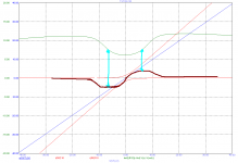
Now, let's plot this stuff and look at the black curve, which depicts the combined gm (of top and bottom tranny). Contrary to my previous post of gm, the green curve, this one doesn't show the 'doubling' at large currents. Instead, only a small increase in the crossover zone. This is because the circuit is a bit over biased (which is another story).
Despite the fact we have taken into account the effect of Vbe, RE' and RE, this kind gm does not explain the excess of distortion caused by a sliding bias.
Please tell me what I did wrong.
Cheers,
E.
Attachments
Please tell me what I did wrong.
The usual confusion between a small signal, linearized, and a large signal analysis. gm=Ic/26mV holds for small signal only. For large signal, Gm(0)=gm/2 where "0" stands for Vo=0. In fact, Gm depends strongly on the output level Vo (otherwise, for example, a bipolar oscillator would not work).
There is no simple way to calculate the large signal transconductance. The large signal analysis of an emitter follower with Re does not have any known analytical closed solution.
I wrote: gm ~=Ic/26mV and notice the tilde.
Whether this equation is correct doesn't matter, as I didn't use it for any calculation at all. My simulator did the calculations, which also takes care of large signal and other effects. And please don't start whining again about the accuracy of simulators. For the purpose at hand they are accurate enough.
The point is that the composite gm of the bipolar output trannies plus emitter resistors did not reveal the gm doubling at large currents. That means you can't use it for explaining the distortion. Perhaps you forgot it, but we are talking about the real cause of distortion: is it bias voltage modulation or is it gm modulation. According to my last plot (black curve) it is not gm modulation.
edit: the astute reader would notice that the 'green' gm curve does show gm doubling. So, wtf are we talking about?
Well, the 'green' gm has taken into account the effect of bias voltage modulation, while the 'black' gm does not.
Last edited:
- Status
- This old topic is closed. If you want to reopen this topic, contact a moderator using the "Report Post" button.
- Home
- Amplifiers
- Solid State
- Class i