Yes to your Sankens
No, you do not need to match transistors...it is not that bad if matched... in the reality it is good to be matched....but this is no mandatory.... if you decide to match, then match the first two, the differential pair...but when you order, usually they come from the same batch and are matched... 20 percent difference is already "matched" (considered, understood as) for analog use.
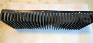
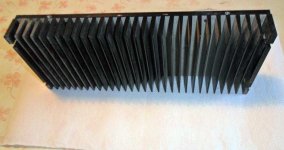
About heatsink.... i am no able to say.... please inform number of fins and shape..better to post a picture or a sketch.... it looks your fins are 12 by 4 centimeters..but i need to know if all fins are the same size, the position of these fins..and the quantity of these fins...well... the informs you gave me are not enougth.
Yes, you can polarize to class AB adjusting the trimpot...put is in between 65 and 95 miliamps and you gonna have an excellent class AB amplifier....you can also remove the zener diode if you want, because it will reduce DC bias to 30 mA under high power...you can keep or remove it...your decision.... it is better to keep it there.
regards,
Carlos
No, you do not need to match transistors...it is not that bad if matched... in the reality it is good to be matched....but this is no mandatory.... if you decide to match, then match the first two, the differential pair...but when you order, usually they come from the same batch and are matched... 20 percent difference is already "matched" (considered, understood as) for analog use.
About heatsink.... i am no able to say.... please inform number of fins and shape..better to post a picture or a sketch.... it looks your fins are 12 by 4 centimeters..but i need to know if all fins are the same size, the position of these fins..and the quantity of these fins...well... the informs you gave me are not enougth.
Yes, you can polarize to class AB adjusting the trimpot...put is in between 65 and 95 miliamps and you gonna have an excellent class AB amplifier....you can also remove the zener diode if you want, because it will reduce DC bias to 30 mA under high power...you can keep or remove it...your decision.... it is better to keep it there.
regards,
Carlos
Last edited:
About heatsink.... i am no able to say.... please inform number of fins and shape..better to post a picture or a sketch.... it looks your fins are 12 by 4 centimeters..but i need to know if all fins are the same size, the position of these fins..and the quantity of these fins...well... the informs you gave me are not enougth.
Thank you for this answer.
I n 'ai not make dust, çà made more than twenty years qu 'ils are in my loft!
All the best!
Attachments
Last edited by a moderator:
 Salut Project16 - bienvenue a diyAudio.
Please read this thread before posting more photos.
http://www.diyaudio.com/forums/everything-else/183084-pictures-why-not-attach-them.html
I have fixed your photos.
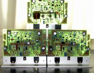
180 watts RMS of audio power, continuous, can be dissipated by this heatsink
Answering Soheil and Project 16
Soheil If your environment is 30 degrées celsius and if you accept 15 degrées celsius of increase of temperature that may go to 45 degrées celsius.
This is what the heatsink can face...audio amplifier power..not heat watts.... Class AB audio amplifier power..continuous, undistorted, sinusoidal and continuous.
But music is average..so.... twice of that is safe... 360 is safe.
This way i do think you heatsink will do the job to 8 and 4 ohms..but you ay need a fan blower if you push the amplifier to 300 watts RMS..then two channels assembled in this same heatsink will not be stable...as gonna need a heatsink able to face 600 watts RMS when your will be good (more or less) to 360W...or more, if your environment has lower temperature than mine.
Good heatsink..... not good....excelent!
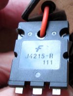
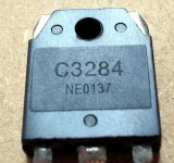
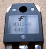
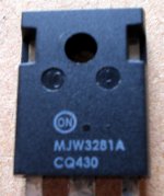
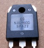
Project 16... About transistors..the ones pointed are able to face 2 ohms loads...others will not survive and may be fried.... if you use others, then do not use 2 ohms loads or strange speakers that has impedance valleys due to internal passive crossover or even speaker itself.
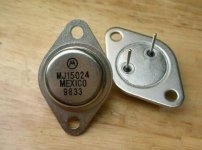
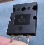
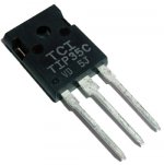
All power transistors can be used..even the famous 2SC5200 and 2SA1943, they are almost the same...all they cousins...even old MJ15024 can be used, and several others..they are one copy or the other..all them result of the now a days actual development....use the ones are available, the ones you like and be happy, because better sonics you may have with 2SC2922 from Sanken..but it is so small the difference that does not make this one to be the choice....it is the same if you increase treble into a tone control from 12 hours to 1 hours and a half...not that big difference..in treble only, you can compensate this with your speaker positioning and adjustment of the +3DB switch...or even removing absortion material around..moving the speaker or installing ceramic tiles below the speaker stand.
J4215, 2SC3281, NJL3281, NJL4281, and many others...there are hundreds that can face more than 100 volts and more than 10 amperes, for audio purposes.
regards,
Carlos
Answering Soheil and Project 16
Soheil If your environment is 30 degrées celsius and if you accept 15 degrées celsius of increase of temperature that may go to 45 degrées celsius.
This is what the heatsink can face...audio amplifier power..not heat watts.... Class AB audio amplifier power..continuous, undistorted, sinusoidal and continuous.
But music is average..so.... twice of that is safe... 360 is safe.
This way i do think you heatsink will do the job to 8 and 4 ohms..but you ay need a fan blower if you push the amplifier to 300 watts RMS..then two channels assembled in this same heatsink will not be stable...as gonna need a heatsink able to face 600 watts RMS when your will be good (more or less) to 360W...or more, if your environment has lower temperature than mine.
Good heatsink..... not good....excelent!
Project 16... About transistors..the ones pointed are able to face 2 ohms loads...others will not survive and may be fried.... if you use others, then do not use 2 ohms loads or strange speakers that has impedance valleys due to internal passive crossover or even speaker itself.
All power transistors can be used..even the famous 2SC5200 and 2SA1943, they are almost the same...all they cousins...even old MJ15024 can be used, and several others..they are one copy or the other..all them result of the now a days actual development....use the ones are available, the ones you like and be happy, because better sonics you may have with 2SC2922 from Sanken..but it is so small the difference that does not make this one to be the choice....it is the same if you increase treble into a tone control from 12 hours to 1 hours and a half...not that big difference..in treble only, you can compensate this with your speaker positioning and adjustment of the +3DB switch...or even removing absortion material around..moving the speaker or installing ceramic tiles below the speaker stand.
J4215, 2SC3281, NJL3281, NJL4281, and many others...there are hundreds that can face more than 100 volts and more than 10 amperes, for audio purposes.
regards,
Carlos
Attachments
Last edited:
So, use the one you like, the one is available and avoid low impedance loads
Just that.
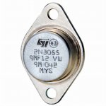
Difference in sonics exist..but not that important..the amplifier is so good that will play excelent sound with ANY power transistor.... even 2N3055.
Why i have suggested the big ones.....because huge....can face 2 ohms.... that was the reason why..others are a little bit weaker.
Type your transistor numbers in google and then type datasheet....there you gonna fin the complementary to all these ones.
I have authorized a Brazilian to explore the Fet in the output, and i said to him:
- "you will not like the sound... a hell strange and mufled!"
then i did the circuit and asked him to make it better and to tweak a lot and to modify...no result..he have not offered the unit to be published....because obvious reason...BGT sound better.
I said...here is the schematic, a sketch.... start from this one and make it sound good...no result till today.... two monthes passed.
regards,
Carlos
Just that.
Difference in sonics exist..but not that important..the amplifier is so good that will play excelent sound with ANY power transistor.... even 2N3055.
Why i have suggested the big ones.....because huge....can face 2 ohms.... that was the reason why..others are a little bit weaker.
Type your transistor numbers in google and then type datasheet....there you gonna fin the complementary to all these ones.
I have authorized a Brazilian to explore the Fet in the output, and i said to him:
- "you will not like the sound... a hell strange and mufled!"
then i did the circuit and asked him to make it better and to tweak a lot and to modify...no result..he have not offered the unit to be published....because obvious reason...BGT sound better.
I said...here is the schematic, a sketch.... start from this one and make it sound good...no result till today.... two monthes passed.
regards,
Carlos
Attachments
Last edited:
Dear Meanman, Juan Vargas internet was out from the air
His internet was down.
I have reserved to your the pcboards.... so, anytime you want... reserved!
Listen boys...and tell me if you can listen so good sound with these cheap dirty damaged poor awfull speakers..... this is because this amplifier.... plays good with any speaker.
The ones have assembled, Brazilians and Juan Vargas, just cannot stop to listen at it...ask them and you gonna know they are astonished!
http://www.youtube.com/watch?v=X88G02PSp7A
Uncle charlie has a forum, please subscribe to be the first 100 guys there...it gonna be one of the best foruns in this world in a matter of 10 years:
http://ww2.eletroforum.com.br/dxamp/index.php
regards,
Carlos
Last edited:
Thank you for your answer on the heatsink.
For my speakers i think that it is good , here is the model.
Elipson - Prestige 3
Friendly, Olivier!")
Project 16... About transistors..the ones pointed are able to face 2 ohms loads...others will not survive and may be fried.... if you use others, then do not use 2 ohms loads or strange speakers that has impedance valleys due to internal passive crossover or even speaker itself.
For my speakers i think that it is good , here is the model.
Elipson - Prestige 3
Friendly, Olivier!
Merci beaucoup monsieur, thanks, helped me a lot and i have concluded and realised...
that i forgot a very important feature into the pcboard.(%#@%*).... sadly my 62 years old are showing effect...i forgot the protection fuse to the ouput speakers.
Your expensive speaker reminded me that..... and people asking for other transistors also made me thing about.
Using other transistors, the possibility to have a damage increase a lot.... people mistake about the type of speaker they will be using (not your case..yours is safe) can become a tragedy....if the output transistors, a more weak version from the sugested ones, be fried in operation...then a supply polarity will appear in the output....if the NPN fry, then +42 volts will cross the speaker coil and will destroy it....if the PNP fry, then -42 volts will cross the speaker coil and will destroy it... so...the use of other transistors, added to the missed output fuse, is a very dangerous combination.... having the cooperation of a young crazy guy that goes paralleling speakers...then ...boooom!
Reason why i am suggesting, now!, people to install, outside the pcboard, fuses in series with the speakers.... use 3.5A fuse (slow blow) to 8 ohms speaker, and 7A fuse or 8A fuse (slow blow) to 4 ohms and 15A fuse to 2 ohms speakers.
Power amplifier fuses are half of that... 1.75 or 2A fuses to 8 ohms..... 3.5A fuses to 4 ohms operation and 8A fuses for 2 ohms operation...there are two fuses in the power amplifier pcboard, one for the positive rail and other for the negative rail.
Yes...the rail fuses may melt and protect...but just in case..put a speaker fuse too.
Do not be scared.... using the suggested huge transistors nothing will happens...i have saturated the amplifier for long time..when it was very hot, i have disconnected the fan blower..i have use 2 ohms together 2uf in the output and nothing happened...but if people try weaker transistors together 2 ohms....then....something bad can happen.
Attachments

Last edited:
Here is the loudspeaker protection we have used with the Dx Blame ST
Amplificadores DX Blame - Carlos Mergulhão
Mitchel made this one based in Silicon Chip Magazine...i do not know how similar or different it is compared with the Silicon Chip Magazine text.... in my imagination he may have used the idea and not the circuit itself.
It can be used with the Dx Super A.
pcboard must be made by yourself, etch at home..we have no more boards available.
regards,
Carlos
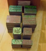
The idea is to allow them to use pcboards already provided
100 guys have assembled in Brazil having these green boards...more 100 guys have assembled using the Supercharged blue boards*, so, they already have their green pcboards to be adapted...they will use fan blower and will not install 2 ohms speaker anyway.
This was an effort to allow them to use the old pcboards they still have without the need to make another one or to have the need to order new pcboards...they can operate Class AB high biased to 90 miliamperes or even use 250 miliamperes without having the DC bias reduction we have in the Dx Super A.... other options to them to continue with their pcboards.
There are several options... Super A, High bias Dx Blame ST operating class AB and normal bias Dx Blame ST operating class AB (30 mA) but using the new tune Dx Super A circuit values.
It is "a la carte" service.... customized to my friend's needs.
This amplifier is an old story that started with the Dx amplifier and evoluted passing to be several new models with different power and features, but keeping the main frame..the skeleton came from the Blameless amplifier from Doctor Self...tweaked an evoluted till the bones...a sequence in the diy brandname evolution...it has a history and more than 200 kits were provide to Brazilians.... this is an effort not to allow them to loose their pcboards already assembled..they can just substitute some parts to have the upgrade and updated, last model, ultimate model, the Dx Super A...that came and started from the Dx Blame ST...and the Dx Blame ST came from other previous models too...a sequence of models..having something alike, the brand identity.
An old story, and history, posted in several threads and several amplifiers...a very long run that i cannot explain you as gonna be a book in size..threads are there for you to watch...type Destroyer x and Dx and you gonna have more than hundred threads.... all this stuff started in 2004 (in this forum)... actually, my search for audio amplifier performance and studies started in 1960.
Dx Super A is a grand, grand, grand, grand, grand, grand, grand, grand son of the Dx amplifier (2004)
Sequence is more or less this one.
Dx Amplifier
HR II
Precision 1
Dx Trust
DHR Turbo
Troyan
Dx Blame ES
Dx Blame ST
Dx Supercharged
Dx Blame MKIII Hx
Dx Blame MKIII - Home Edition
Mako
Dx Super A
New amplifier to come to release July 2014 at my own forum first...in December in diyaudio too... Mako II
* http://www.nabucoeletronica.com.br/dx/home.html
regards,
Carlos
Attachments
Last edited:
Good Project 16, i will look forward to your posts about
Votre décision est parfait... your decision is perfect...i ensure you that you will never regret about that.... never!
Today, me and Juan, we gonna torture the amplifier:
http://www.youtube.com/watch?v=ojDjamHISxY
regards,
Carlos
Votre décision est parfait... your decision is perfect...i ensure you that you will never regret about that.... never!
Today, me and Juan, we gonna torture the amplifier:
http://www.youtube.com/watch?v=ojDjamHISxY
regards,
Carlos
Hello destroyer X!
I have the solution to fit my transistors (Sanken) a printed circuit board against but I have a doubt about their position on the heatsink.
In fact they are positioned either on the bottom or on the top of the heatsink.
Ideally in the center but it is hard to do.
There will be a problem of heat dissipation and if they are positioned?
Thank you again!
Power transistors goes atop of the heatsink naturally
But we will need an "L" shape adaptor that you can see watching this video, it is an "L" shape profile.
Dx Supercharged Blue pcboards available - YouTube
regards,
Carlos
But we will need an "L" shape adaptor that you can see watching this video, it is an "L" shape profile.
Dx Supercharged Blue pcboards available - YouTube
regards,
Carlos
All this depends the power you want....or the speaker impedance you will use
It can put out more or less 70 watts at low distortion... can go more, with reasonable distortion, can reach 90 watts RMS at 8 ohms.... in this case you have the need of 150 to 180 watts (VA) transformer to 1 channel.... to each channel .... if you decide to use a single transformer and a single supply to feed two channels, then you must have a 300 to 360 watts (VA) power transformer..depending if you adjust your volume lower than the threshold of distortion or higher than the threshold of distortion....this depends on the music you play and the volume you like to play and how sensitive are your ears to clipping and harmonic distortion....
Transformers are 30 plus 30 volts AC, because after rectification and filtering you gonna have a resultant DC voltage of 42 plus 42 volts.
So, first answer goes to 8 ohms.....transformer should be 150 watts(VA) each if you intend to buy two transformers........or 300 watts (VA) to feed two channels using a single transformer.
So, second answer goes to 4 ohms speakers.... transfomer should be twice the above current.... 300 watts each one of two transformers if you intend to buy two transformers and to make two separated supplies, each one of them to feed one channel...or 600 watts (VA) single transformer if you intend to use a single power supply.
So, third answer goes to 2 ohms speakers.... transformer should be twice the above current, or 600 Watts (VA) each one of two transformers if you intend to buy two transformers and to make two separated supplies (transformer, plus rectifiers plus filters).... but if you decide to use a single power transformer to feed two channels..then the choice will be 1200 watts power transformer.
This amplifier can put out aproximatelly 70 watts at 8 ohms each channel, 150 watts at 4 ohms to each channel and can reach 320 watts rms to each channel at 2 ohms loads.
Fuses to the positive and negative rails should be:
8 ohms speakers = 1.5A plus 1.5A...these goes into the audio amplifier pcboard...output series fuse can be 3 to 3.5 amperes..slow blow fuses.
4 ohms speakers = 3A plus 3A ... these ones goes into the audio amplifier pcboard .... output series fuse to the speaker can be 6 amperes.
2 ohms speakers = 6A plus 6A ... these ones goes into the audio amplifier pcboard.. output series fuse to the speaker can be 12 amperes.
Electrolitic condensers for filtering you calculate... use 5000uf to each ampere...so....if your supply will power a single pcboard at 8 ohms...then it is 1.5 plus 1.5 amperes..then put 7500uf plus 7500uf or more as filters...rectifiers should be twice this power.
You see that for 2 ohms you gonna need 30 thousand microfarads to each rail...so... 30K plus 30K...and this to a single power amplifier..reason why i suggest you to use a series pass regulator that has capacitance multiplier effect or search for something alike Dx Power Supply..... you can find it at the Power Supply forum.... for sure others may fit, the electronic filtering reduces the ammount of capacitance from several electrolitics....this is too much expensive when you drain high current.
Primary fuses you divide the power of your transformer expressed in watts by your mains voltage...then you have the fuse, use the value or the immediate superior value found in the market.
Heatsinks:
To each 10 watts of audio power ( the maximum power you gonna reach depends your transformer power and depends on your speaker impedance) then use an aluminum blade of 10 by 10 centimeters (4 inches by 4 inches..so..squared)...this is the equivalent size to 10 watts of AUDIO power... so.... depending your power you can evaluate your heatsink...use fan blower anyway... this heatsink dimension (tested in laboratory, under 30 degrées centigrades environment being able to face a 10 watts RMS audio amplifier, operating class AB or class B, having sinusoidal signal in the output, undistorted or unclipped waveform)
This is to continuous.... music is average.... this results twice the needed size for music...so...you can calculate.
But Class A and Super A operation is different..generates too much heat and these calculation does not make any sense.... reason why i suggest to install fan blower having LM7808 or even LM7805 or other manufacturer, voltage regulator integrated circuits to power the fan, reducing voltage will reduce fan speed and fan noise....but be attention, these Voltage Regulator Chips have a limit of input voltage you should see in the datasheet.
regards,
Carlos
- Home
- Amplifiers
- Solid State
- Dx Blame ST together Dx Super A