Indeed, I had to persist to find the cause of very strange fault in my CD-player, but eventually (2 years later), I did.
That ones going back a bit. Must have missed it first time around so well done
") Faults like that are real odd balls but its really satisfying to stick with them and fix them.
Faults like that are real odd balls but its really satisfying to stick with them and fix them. Reminds of a guy at work (this was years ago and... and he was one of our best bench techs) who had an Hitachi D980 ? top of the range cassette deck and it would always throw a wobbler at the most inconvenient time by shutting off or going into some wrong mode. He'd checked absolutely everything you could think of so in frustration brought it into work for a joint effort.
Long story short, and I said as a joke that all that was left were the fuses on the PCB. Reply "if that fixes it you can have it" Hitachi x*7"3&^* junk. Guess what
We replaced them and it never missed a beat afterward. The wire must have parted at the end caps or something. It was so funny... he kept the deck though.so if dtm1962 is reading all this. Well we'll get a result with this one too
so if dtm1962 is reading all this. Well we'll get a result with this one too
Yes I am home now and I am going to do all measurements and plot on a marked up schematic. I will measure the frontend right thru to the Q617...
Stay tuned...
Thanks,
Update on Measurements
Hi Guys : Please review the 3 (actually 4 sets of measurements) attachments
Observations & Notes:
1) Lifted one lead of all 3 Polystyrene pF range caps - no effect....
2) Measured Q613 (Black on C & Red on E) in Mohm range = measures OPEN
3) Measured Q615 (Red on C & Black on E) in Mohm range = measures OPEN
4) All measurements on 3 attachments is with Q617 shorted (C & E)
Attachment # 1 Q613 BASE lifted
Attachment #2 Q613 IN CIRCUIT
Attachment #3A Q613 REMOVED
Attachment #3B Q613 & Q615 REMOVED
My feeling is that Q613 is SHORTED & Q615 IS OPEN.
Let me know what you think.
Thanks in advance,
Attachments
What I find remarkable is the difference in currents through R623 with each measurement.
First set: 52 mA;
Second set: 15 mA;
Third set A: 66.7 mA ???? With Q613 removed, both ends of R623 should read the same voltage (i.e. 0 mA current). This looks like an error in measurement, please repeat.
Third set B: unknown, I'd like to know the value in this situation too, just to rule out leakage across the PCB (unlikely but not impossible).
Q613 sure looks questionable to me.
Edit: Q615 cannot be open. If that were the case, the voltage across R629 would be 0 V.
In the first two sets of measurements, it's open and conducting 38 mA, in the last it's not and the current drops to near 0, as expected.
Last edited:
Even with the BASE of Q613 LIFTED from the circuit, I measured +51.3 VDC on the BASE PIN which was "floating above the PCB". So does that say the EMITTER (@ +56.7VDC) was leaking to the BASE?
Let me know.
Thanks,
Firstly, I think Q613 has to be duff
It has to give the same result (voltage on Q617) when the base is disconnected and the same when the transistor is removed. Only variable in the test conditions I can see was that C613 was present for one test and not the other ? Lets not overlook anything. With a good transistor fitted and the base lifted you would measure essentially the same voltage on B and E. That would be normal. What isn't normal with your readings is that with the base lifted the transistor should be totally off and non conducting.
Your DVM readings on Meg ohm range (which must done with the transistor removed and on the table in front of you
) don't appear to show an obvious leakage but that isn't conclusive. Transistors can break down under voltage and readings can be a bit "meter specific"Another thought in trying to cover all bases on this. Is Q613 an original device or a replacement from somewhere ? Just thinking if it wasn't what it was supposed to be and all that
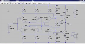
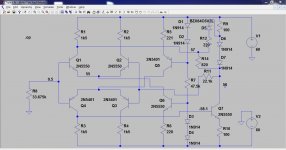
Have a look at this Ltspice simulation. I wanted to prove to myself that this all worked (which it does) doing what I have been outlining. I have marked the voltages on the circuit.
Here are the DC voltages with Q617 shorted. You'll see the voltage at this point settles to near zero as expected. I also open circuited Q613 base and the voltage at Q617 was still near zero. So we are still looking at Q613
Here's the file if you want to try it
Here are the DC voltages with Q617 shorted. You'll see the voltage at this point settles to near zero as expected. I also open circuited Q613 base and the voltage at Q617 was still near zero. So we are still looking at Q613
Here's the file if you want to try it
Attachments
Is it possible to simulate leakage of Q8 by placing a highish resistor between C and E?
For ordinary leakage I would say yes. I'm just thinking if say the real transistor broke down at high volts or started "zenering" or some combination of inter junction leakage etc then the simulation might not compare to the actual real world faulty device.
Try it... the file should be good to go and modify
Eureka!
I replaced the 2SA1142 with a brand new 2SA1249 and I get all the right voltages
So now I have to find some new Genuine 2SA1142 & spare 2SC2682 for the amp.
Question: Can I use the higher current 2SA1249 & 2SC3117 in its place or should I try to source these original & very hard to get transistors?
I will reinstall the 2SA1208 & ite NPN partner to see if the voltages remain as well as removing the shorted feedback resistor.... but I will leave the bulb in the ADC line for now.
Does anyone have any 2SA1142 for sale?
Let me know.
Thanks,
Dan
Firstly, I think Q613 has to be duff
With a good transistor fitted and the base lifted you would measure essentially the same voltage on B and E. That would be normal. What isn't normal with your readings is that with the base lifted the transistor should be totally off and non conducting.
Your DVM readings on Meg ohm range (which must done with the transistor removed and on the table in front of you
Another thought in trying to cover all bases on this. Is Q613 an original device or a replacement from somewhere ? Just thinking if it wasn't what it was supposed to be and all that
I replaced the 2SA1142 with a brand new 2SA1249 and I get all the right voltages
So now I have to find some new Genuine 2SA1142 & spare 2SC2682 for the amp.
Question: Can I use the higher current 2SA1249 & 2SC3117 in its place or should I try to source these original & very hard to get transistors?
I will reinstall the 2SA1208 & ite NPN partner to see if the voltages remain as well as removing the shorted feedback resistor.... but I will leave the bulb in the ADC line for now.
Does anyone have any 2SA1142 for sale?
Let me know.
Thanks,
Dan
Good to know you're getting somewhere!
Personally, if (genuine) 2SA1142s were unavailable, I'd go for a close replacement.
I would also change out its complementary (in this case Q615) for the complementary of the new Q613.
2SA1142's complementary is 2SC2682;
2SA1249's complementary is 2SC3117.
And if this proved successful, I'd change the same pair in the other channel as wel to keep things identical.
I can't advize from the top of my head on which transistor is a suitable replacement, perhaps someone else here can?
Last edited:
Thats brilliant news
Before we jump in and rebuild it all there should really be another test Its up to you if you want to do this but whether or not it is important that the bias is set to minimum before the output stage is re-connected and powered up.
The test is to confirm the vbe multiplier is working correctly as this is vital to ensure the output stage doesn't draw excess current (and I can't see there being a problem here). All this test does is confirm that the voltage across Q617 varies smoothly and correctly as the preset is turned. The 2SD1953 is an "oddball" darlington type and I'll be honest and say I'm not 100% sure what you might see here. The range of adjustment seems very small looking at the circuit values around Q617.
So what we do is this,
1. Remove the link across Q617. (Leave the 22K feedback resistor still tagged to Q617 C or E).
2. The preset VR601 is adjusted for maximum resistance. This means that the resistance between B and E of Q617 is at its highest (about 8.39K... the 6.19K + 2.2K added together).
3. We now need to monitor the voltage across Q617 C and E and in order to do this safely and with no possibility of slips I would tag two wires to Q617 and extend them out to your meter.
4. Switch on and observe the voltage as the pot is turned. It should vary from around (and this is where I am unsure) from around 2 volts to perhaps 4 volts or so. Record and post the result of the max and min voltages
5. If that is OK then return the pot to give minimum voltage across Q617.
Transistors...
I would say not very critical as the design is heavily compensated and not very reliant on transistor characteristics for correct operation. So it all depends on what you can get. The ancient MJE340 and MJE350 make excellent drivers and I'd have no hesitation in trying those. Others are the 2SB649A and 2SB669A (must be A type for voltage rating) and the more modern 2SA1209 and 2SC2911.
As Jitter mentions, when its all done I would use the same devices in both channels. Be very careful where you buy semiconductors from as there are a lot of fakes out there.
Before we jump in and rebuild it all there should really be another test
Its up to you if you want to do this but whether or not it is important that the bias is set to minimum before the output stage is re-connected and powered up. The test is to confirm the vbe multiplier is working correctly as this is vital to ensure the output stage doesn't draw excess current (and I can't see there being a problem here). All this test does is confirm that the voltage across Q617 varies smoothly and correctly as the preset is turned. The 2SD1953 is an "oddball" darlington type and I'll be honest and say I'm not 100% sure what you might see here. The range of adjustment seems very small looking at the circuit values around Q617.
So what we do is this,
1. Remove the link across Q617. (Leave the 22K feedback resistor still tagged to Q617 C or E).
2. The preset VR601 is adjusted for maximum resistance. This means that the resistance between B and E of Q617 is at its highest (about 8.39K... the 6.19K + 2.2K added together).
3. We now need to monitor the voltage across Q617 C and E and in order to do this safely and with no possibility of slips I would tag two wires to Q617 and extend them out to your meter.
4. Switch on and observe the voltage as the pot is turned. It should vary from around (and this is where I am unsure) from around 2 volts to perhaps 4 volts or so. Record and post the result of the max and min voltages
5. If that is OK then return the pot to give minimum voltage across Q617.
Transistors...
I would say not very critical as the design is heavily compensated and not very reliant on transistor characteristics for correct operation. So it all depends on what you can get. The ancient MJE340 and MJE350 make excellent drivers and I'd have no hesitation in trying those. Others are the 2SB649A and 2SB669A (must be A type for voltage rating) and the more modern 2SA1209 and 2SC2911.
As Jitter mentions, when its all done I would use the same devices in both channels. Be very careful where you buy semiconductors from as there are a lot of fakes out there.
Thats brilliant news
Before we jump in and rebuild it all there should really be another test
The test is to confirm the vbe multiplier is working correctly as this is vital to ensure the output stage doesn't draw excess current (and I can't see there being a problem here). All this test does is confirm that the voltage across Q617 varies smoothly and correctly as the preset is turned. The 2SD1953 is an "oddball" darlington type and I'll be honest and say I'm not 100% sure what you might see here. The range of adjustment seems very small looking at the circuit values around Q617.
So what we do is this,
1. Remove the link across Q617. (Leave the 22K feedback resistor still tagged to Q617 C or E).
2. The preset VR601 is adjusted for maximum resistance. This means that the resistance between B and E of Q617 is at its highest (about 8.39K... the 6.19K + 2.2K added together).
3. We now need to monitor the voltage across Q617 C and E and in order to do this safely and with no possibility of slips I would tag two wires to Q617 and extend them out to your meter.
4. Switch on and observe the voltage as the pot is turned. It should vary from around (and this is where I am unsure) from around 2 volts to perhaps 4 volts or so. Record and post the result of the max and min voltages
5. If that is OK then return the pot to give minimum voltage across Q617.
Transistors...
I would say not very critical as the design is heavily compensated and not very reliant on transistor characteristics for correct operation. So it all depends on what you can get. The ancient MJE340 and MJE350 make excellent drivers and I'd have no hesitation in trying those. Others are the 2SB649A and 2SB669A (must be A type for voltage rating) and the more modern 2SA1209 and 2SC2911.
As Jitter mentions, when its all done I would use the same devices in both channels. Be very careful where you buy semiconductors from as there are a lot of fakes out there.
Alright sounds good .... I will need a little time to order some parts and I will update later next week.
Thanks again for everyone's help.
Stay tuned....
- Status
- This old topic is closed. If you want to reopen this topic, contact a moderator using the "Report Post" button.
- Home
- Amplifiers
- Solid State
- Help Needed: Excessive DC Offset/Imbalance - Rotel RB-990BX Power Amp