Hei Mooly if you are so ""willing "" with simulator i think i will send you a few circuits to simulate for me ( second opinion is always something to listen to )
I have a few ideas id like to share but i am not that good in simulators
I have an example also that i would like to talk about Can i Pm you ?
Sorry for the off topic
Kind
regards
sakis
I have a few ideas id like to share but i am not that good in simulators
I have an example also that i would like to talk about Can i Pm you ?
Sorry for the off topic
Kind
regards
sakis
UPDATE: So...I have a counterfeit transistor for Q613 (2SA1142)
So guess what?
The PNP 2SA1142 measures as a NPN!!! Via Diode test and hfe test... D*MN!
Since the original NEC 2SA1142 is a green body unit.....and this was a black body unit....I should have noted...
It is a rebadged NPN from China.... D*MN!!!!
It just didn't seem like it was possible being a basic cheap transistor..
It teaches me a lesson to check each one before I put it in the circuit.
I just didn't see this coming! I'm mad at myself!
Lesson learned...
Just Move on....
I will let you know when it is all back together & working...
Performed Test to check for Vbe correct operation
So I performed the above test and here are the results:
Minimum voltage across Q617 is 3.25V & maximum is 3.68V when adjusting the pot.
22K resistor attached to Q617 E
3.2V drop across Q617 C & E
1.2V drop across Q617 B & E
2.0V drop across Q617 B & C
Relative to ground:
Q617 E is 0.2V
Q617 B is 1.4V
Q617 E is 3.4V
Question:
If the feedback resistor is not connected to Q617, I do get voltages near +Rail voltage (~3-4volts less than +Rail voltage)
for all 3 measurements with the .6V across the junctions (BE & CE etc.).
Is this normal or does it point to other remaining problem.... other than the
so called Counterfeit PNP 2SA1142 which is actually a NPN.
Let me know what you guys think
Thanks
Thats brilliant news
Before we jump in and rebuild it all there should really be another testIts up to you if you want to do this but whether or not it is important that the bias is set to minimum before the output stage is re-connected and powered up.
The test is to confirm the vbe multiplier is working correctly as this is vital to ensure the output stage doesn't draw excess current (and I can't see there being a problem here). All this test does is confirm that the voltage across Q617 varies smoothly and correctly as the preset is turned. The 2SD1953 is an "oddball" darlington type and I'll be honest and say I'm not 100% sure what you might see here. The range of adjustment seems very small looking at the circuit values around Q617.
So what we do is this,
1. Remove the link across Q617. (Leave the 22K feedback resistor still tagged to Q617 C or E).
2. The preset VR601 is adjusted for maximum resistance. This means that the resistance between B and E of Q617 is at its highest (about 8.39K... the 6.19K + 2.2K added together).
3. We now need to monitor the voltage across Q617 C and E and in order to do this safely and with no possibility of slips I would tag two wires to Q617 and extend them out to your meter.
4. Switch on and observe the voltage as the pot is turned. It should vary from around (and this is where I am unsure) from around 2 volts to perhaps 4 volts or so. Record and post the result of the max and min voltages
5. If that is OK then return the pot to give minimum voltage across Q617.
So I performed the above test and here are the results:
Minimum voltage across Q617 is 3.25V & maximum is 3.68V when adjusting the pot.
22K resistor attached to Q617 E
3.2V drop across Q617 C & E
1.2V drop across Q617 B & E
2.0V drop across Q617 B & C
Relative to ground:
Q617 E is 0.2V
Q617 B is 1.4V
Q617 E is 3.4V
Question:
If the feedback resistor is not connected to Q617, I do get voltages near +Rail voltage (~3-4volts less than +Rail voltage)
for all 3 measurements with the .6V across the junctions (BE & CE etc.).
Is this normal or does it point to other remaining problem.... other than the
so called Counterfeit PNP 2SA1142 which is actually a NPN.
Let me know what you guys think
Thanks
Ohhh a counterfeit That explains a lot.
See post #128 here (and the whole thread)
http://www.diyaudio.com/forums/parts/82638-my-transistors-original-copy-7.html#post1311453
As to testing the amp and the feedback resistor connection. The feedback resistor is essential to establish the DC conditions in the amp. What you have with all the front end circuitry is really a discrete "opamp". There are two inputs, the bases of Q601 and 607 and the bases of Q603 and 609. These are the "non inverting" and "inverting" equivalents respectively to an opamp. From only the feedback resistor and R613 we can calculate the gain of the amp.
Operational amplifier - Wikipedia, the free encyclopedia
Your voltages seem "OK" in a broad sense. tbh I would have expected Q617 E (the point where the feedback resistor connects) to be a little nearer to zero.
Although 0.2 volts is low, if that ends up as a DC offset at the output of the amp then it's not really low enough...
I think at this point we say its OK. The amp is missing the "slow" output stage and its conceivable that there could, under the present test conditions, be some small HF instability upsetting the DC readings.
Lets assume its good to go
If the feedback resistor is missing then the voltages on Q617 will swing toward the rails as you have found. So no problem there. Its the voltages across Q617 that determine the bias current in the output stage rather than absolute values above and below ground. The range of adjustment seems a little small as I suspected, but thats down to the resistor values and could equally be called good design as it provides fine adjustment in the right "zone". Nothing worse than presets that are all or nothing and where a degree or two of rotation cause the current to jump wildly.
So set the preset to the end that gives the lowest voltage across C and E of Q617
What I would suggest before initially powering up after replacing the parts is to check carefully that all parts are correctly fitted and that all the caps that you lifted are replaced. Also don't forget to refit the feedback resistor back to its original location.
I would power up the fully rebuilt amp (with the bulb tester of course) initially with Q617 still shorted C and E. The amp should work perfectly like that. The only problem with no bias is that you might hear slight crossover distortion at very low volume.
That explains a lot.See post #128 here (and the whole thread
)http://www.diyaudio.com/forums/parts/82638-my-transistors-original-copy-7.html#post1311453
As to testing the amp and the feedback resistor connection. The feedback resistor is essential to establish the DC conditions in the amp. What you have with all the front end circuitry is really a discrete "opamp". There are two inputs, the bases of Q601 and 607 and the bases of Q603 and 609. These are the "non inverting" and "inverting" equivalents respectively to an opamp. From only the feedback resistor and R613 we can calculate the gain of the amp.
Operational amplifier - Wikipedia, the free encyclopedia
Your voltages seem "OK" in a broad sense. tbh I would have expected Q617 E (the point where the feedback resistor connects) to be a little nearer to zero.
Although 0.2 volts is low, if that ends up as a DC offset at the output of the amp then it's not really low enough...
I think at this point we say its OK. The amp is missing the "slow" output stage and its conceivable that there could, under the present test conditions, be some small HF instability upsetting the DC readings.
Lets assume its good to go
If the feedback resistor is missing then the voltages on Q617 will swing toward the rails as you have found. So no problem there. Its the voltages across Q617 that determine the bias current in the output stage rather than absolute values above and below ground. The range of adjustment seems a little small as I suspected, but thats down to the resistor values and could equally be called good design as it provides fine adjustment in the right "zone". Nothing worse than presets that are all or nothing and where a degree or two of rotation cause the current to jump wildly.
So set the preset to the end that gives the lowest voltage across C and E of Q617
What I would suggest before initially powering up after replacing the parts is to check carefully that all parts are correctly fitted and that all the caps that you lifted are replaced. Also don't forget to refit the feedback resistor back to its original location.
I would power up the fully rebuilt amp (with the bulb tester of course) initially with Q617 still shorted C and E. The amp should work perfectly like that. The only problem with no bias is that you might hear slight crossover distortion at very low volume.
Hmmm, wish I had posted that it had occurred to me a couple of times that it looked like NPN-behaviour in the replacement for Q613. Even the thought it being a counterfeit had crossed my mind but I dismissed it.
Well, at least you've come to this conclusion methodically. And the good news is that it indeed looks like you're good to go!
Well, at least you've come to this conclusion methodically. And the good news is that it indeed looks like you're good to go!
Next Steps
Thanks guys - Mooly & Jitter for sticking with me and my next steps are as follows:
So I:
1) will put back Q619 & Q621 (C2910/A1208) in the circuit
2) add the feedback resistor back to the emitter resistors of the outputs
3) and leave the Q617 C & E shorted
4) leave the bulb in series with AC line
5) power up & make measurements to determine correct voltages/dim light
If everything seems to be fine such as dim light & correct voltages then I will:
1) power down & remove test bulb out of AC line
2) remove the jumper across Q617 C & E
3) add #1 meter across testpoints T1/T3
4) add #2 meter across outputs to measure DC @ outputs
5) power up
6) adjust bias to 7mV
Any flaw to this plan other than maybe adding leaving in the bulb in the circuit
while I begin to adjust bias as I have other channel disconnected and the load
is less than the 60W bulb's influence on the current delivery to amp?
Let me know
Thanks in advance,
Looks good.
Personally, when finished, I would recheck and, if necessary, readjust the bias with the amp in normal working conditions; i.e. without bulb and with both channels connected to power supply.
Thanks Jitter.... I will move forward with this plan and I will leave the bulb in for the 1st adjustments.... just in case...
That all sounds good. I would probably leave the bulb in place after removing the short on Q617. You just never know... and its a good safeguard for an initial power up with the bias generator active. If the bulb is still dim when the short is removed and then begins to glow as the preset is turned you know its looking good. At the first sign of the bulb glowing as the preset is turned, you should then turn it back down, switch off and remove the short and set it up for real.
Once the bulb begins to light then the filament starts to increase in resistance rapidly and that causes the rails to collapse. So its just used for initial testing only. Never attempt to set the bias with the bulb present because the supplies will be a lot lower than normal. Also do not have any speakers connected during any tests or adjustments.
I'm not sure what transistors you actually have fitted at the moment but if they are suitable then there is nothing stopping you testing it out now. As long as the devices fitted are adequately rated then the amp should all work as intended.
Are you happy with Q619/621 that you have and all the rest of the output stage or would you like some more simple tests to see all that part of the circuit is OK first ?
Looks good.
Personally, when finished, I would recheck and, if necessary, readjust the bias with the amp in normal working conditions; i.e. without bulb and with both channels connected to power supply.
We think alike I'll look in later...
That all sounds good. I would probably leave the bulb in place after removing the short on Q617. You just never know... and its a good safeguard for an initial power up with the bias generator active. If the bulb is still dim when the short is removed and then begins to glow as the preset is turned you know its looking good. At the first sign of the bulb glowing as the preset is turned, you should then turn it back down, switch off and remove the short and set it up for real.
Once the bulb begins to light then the filament starts to increase in resistance rapidly and that causes the rails to collapse. So its just used for initial testing only. Never attempt to set the bias with the bulb present because the supplies will be a lot lower than normal. Also do not have any speakers connected during any tests or adjustments.
I'm not sure what transistors you actually have fitted at the moment but if they are suitable then there is nothing stopping you testing it out now. As long as the devices fitted are adequately rated then the amp should all work as intended.
Are you happy with Q619/621 that you have and all the rest of the output stage or would you like some more simple tests to see all that part of the circuit is OK first ?
Hi Mooly:
I have 2 qty SC2910 (Q619) & 3 qty SA1208 (Q621) that measure the same during the hfe test & measure correctly for diode test so I believe these will work.
Here goes.... I will update once complete..... I am assuming its late afternoon in UK/Europe at this time....
Thanks...
Nearly 6.30pm... so we're going for it
Take it slow and check everything along the way.
Good luck
Thanks....
Results so far....
With Q617 shorted everything looks good...
VERY IMPORTANT NOTE (or clue) : even before powered up the DC offset is - 180mV once the meters are hooked up BUT no power....
Powered down and removed short.....
With bulb still in the AC line the bias was must set to 4.0mV just for a start @ +/-50V rail voltages versus +/-71 VDC without bulb...
Light is dim and varies (obviously) with the adjustment of pot....
DC offset stays fairly constant at -180mV which as Mooly noted is too high...
Next step is to take the bulb out of AC line and do the bias correctly.
Concerned about the -180mV DC offset (with or without power)! Is this a transistor matching for the input differential 1016's/2362's or ????
Let me know what you think
Have to do a few errands prior to last test tonight.... 4-5 hours away...
In the meantime.... please add any comments in regards the reasoning for
-180mV of DC ooffset.
Thanks in advance,
This is looking good...
This might sound a silly question but have to ask
The 180mv offset. You should now be measuring the offset by placing the meter directly across the speaker terminals on the amp. Just asking in case you were still measuring to Q617 or from some slightly non standard ground point... nah, thought not ...
I'm not 100% sure how input stage transistor matching would affect this, or should I say to what extent because it will affect the balance. If there really is an offset of 180mv you could try swapping just one pair of either the input NPN's or PNP's over. Q601 for Q603
That said lets put the offset into context. 180mv DC will dissipate only 8 milliwatts in a 4 ohm speaker. So in reality there is certainly no operational worries... just that 180mv is considered to high. A few years ago I think 100mv was deemed an upper limit.
It would be worth comparing with the other channel too.
When you set the bias current for real, follow the procedure in the manual (I haven't looked at that yet) and always recheck when the amp is hot and has been playing loud. If the bias isn't stable and seems to drift with temperature then always aim low rather than high to avoid problems.
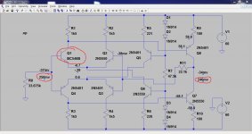
As a quick test I threw changing Q601 in spice and this is the result. The two figures in red are the offsets with Q601 as something different (as in not matched) So yes, matching plays a big part in this configuration... but even if your offset is 180mv its not detrimental to the amp or speaker. Just nice to get it lower
Attachments
Hi Mooly:
Yes it is at the speaker terminals....
Could it be caused by the 8.2kohm & 6.19kohm
as indicated (in the schematic) in the bias circuit as the actual value
On the original circuit was changed to 6.8kohm & 3.9kohm working
in unison with the 2kohm pot? Just a thought?
I will confirm that there is no voltage differential
between the main ground (star grounding) at the 4 caps in power supply
and the speaker ground
Let me know
Thanks
As a quick test I threw changing Q601 in spice and this is the result. The two figures in red are the offsets with Q601 as something different (as in not matched) So yes, matching plays a big part in this configuration... but even if your offset is 180mv its not detrimental to the amp or speaker. Just nice to get it lower
Just noticed your simulation... I will consider this a potential path
forward.
Thanks again
Stay tuned
- Status
- This old topic is closed. If you want to reopen this topic, contact a moderator using the "Report Post" button.
- Home
- Amplifiers
- Solid State
- Help Needed: Excessive DC Offset/Imbalance - Rotel RB-990BX Power Amp