I would guessed 1KVA
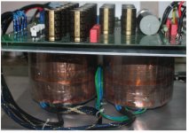
yes, 1KVA for one Transformer 0-58.5V, for Channel amplifier.
Thanks
Hey, which ferrite beads do you use for your FETs? Are they on both pins except the gate? Anyway it's an extremely nice build and looks incredible. Did you get the chassis from siliconray perhaps?
From your latest schematics it looks like this amp is a tweaked Goldmund clone rather than an OPA637.
Are those really ferrite beads or nylon spacers to keep mosfets aligned straight?
Do
hi all!
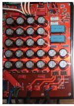
take quite some time, and I finally completed amplifier 637, with such modifications and certain combinations, to invite you to view images!
Thank you
Very nice amplifier!
Which design is it based on? Are PCBs available?
Can you give us the URL of where you bought the chassis?
Thanks
Do
Very nice amplifier!
Which design is it based on? Are PCBs available?
Can you give us the URL of where you bought the chassis?
Thanks
Do
the Design , i can tell exactly in here, Because have some Rule (please see some page before)
only post the PCB and all the value.
The PCB , i can make for all, if you make it, I think you have Amli-end.
Yes, I'm very interested with the PCB. Are you going to make it and available for all DiY'ers? Or is it in the form of Group By? Let us know coz' everybody is waiting and interested to try.
Cheers,
Fredlock
yes, i can share all to you!
thanks
")
a few more pictures, many thanks!
hello.
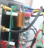
I'm building telos. and wonder what value the inductor 18 t 1,5 cm?
value in mH? maybe I use foil inductor...
hello.
I'm building telos. and wonder what value the inductor 18 t 1,5 cm?
value in mH? maybe I use foil inductor...
Hi!
Please do not say Gm or telos, it is not good for us, That's the rules of the forum.This is 637 amplifier.Thanks and best regards.
And please see it:
wrap 15 round, diameter: 1.5cm to 2cm
Attachments
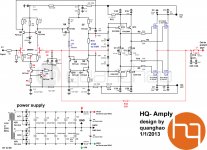
after I copy Goldmun Telos 2500 Amplifier, I was successful and not only that, on the basis of development, diy, and little understanding, learning and experience inherited their predecessors,
Quanghao also to design an amplifier with circuit diagram here. Please see
Thanks all
Quanghao also to design an amplifier with circuit diagram here. Please see
Thanks all
Attachments
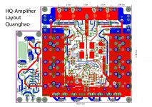
Layout of HQ-Amplifier
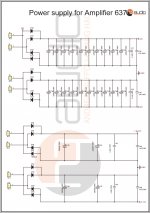
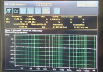
and here is the layout of the HQ-Amplifier, and parameters measured frequency response measurements using Tektronix AM 700, invite you to see, thank you very much!
quanghao
and here is the layout of the HQ-Amplifier, and parameters measured frequency response measurements using Tektronix AM 700, invite you to see, thank you very much!
quanghao
Attachments
Hi Quanghao,
I'm really interested in that amp PCB but would like you to do them in thicker
Board thickness = 2mm, Copper thickness = 70um and possibly gold plating on solder pads
The previous PCBs were too thin for my taste. I don't mind paying a little extra for better PCB.
Thanks
Do
I'm really interested in that amp PCB but would like you to do them in thicker
Board thickness = 2mm, Copper thickness = 70um and possibly gold plating on solder pads
The previous PCBs were too thin for my taste. I don't mind paying a little extra for better PCB.
Thanks
Do
Hi Quanghao,
I'm really interested in that amp PCB but would like you to do them in thicker
Board thickness = 2mm, Copper thickness = 70um
yes 2mm
and possibly gold plating on solder pads
i can not do that,
Thanks
Hi Quanghao,
I'm really interested in that amp PCB but would like you to do them in thicker
Board thickness = 2mm, Copper thickness = 70um
yes 2mm
and possibly gold plating on solder pads
i can not do that,
Thanks
Why not? Is it a cost issue or your PCB provider does not do it?
What about 70um copper thickness?
Thanks
Do
Why not? Is it a cost issue or your PCB provider does not do it?
What about 70um copper thickness?
It is may be!
Thanks
Why not? Is it a cost issue or your PCB provider does not do it?
What about 70um copper thickness?
It is may be!
Thanks
OK, I'm interested, please let us know the price per PCB.
Thanks
Do
The feedback connection to D3 and D4 makes the stability under clipping very complex and conditional. I can't predict what will set it off but it seems dangerous.
Also, if the Cj of the zeners is significant compared to the 4148's, then you will probably have charge pumping through the 4148's causing some strange dynamic frequency-dependent distortion. Whether this is is perceived as distortion or as some "special sound quality" is another matter. If you flip the D+Z around, it'll be the 4148 that's reverse-biased rather than the Zener, so its small capacitance will be more guaranteed and charge-pumping reduced. The original Goldmund actually does this IIRC, and although it doesn't look right it still works. If you choose to switch the protection back to the output I suggest to put 2 diodes in series with R19 so it's value can be decreased - because with the Goldmund protection scheme the gate voltage at clipping is Vz+Vd+(Ivasmax*R19).
Also, if the Cj of the zeners is significant compared to the 4148's, then you will probably have charge pumping through the 4148's causing some strange dynamic frequency-dependent distortion. Whether this is is perceived as distortion or as some "special sound quality" is another matter. If you flip the D+Z around, it'll be the 4148 that's reverse-biased rather than the Zener, so its small capacitance will be more guaranteed and charge-pumping reduced. The original Goldmund actually does this IIRC, and although it doesn't look right it still works. If you choose to switch the protection back to the output I suggest to put 2 diodes in series with R19 so it's value can be decreased - because with the Goldmund protection scheme the gate voltage at clipping is Vz+Vd+(Ivasmax*R19).
- Status
- This old topic is closed. If you want to reopen this topic, contact a moderator using the "Report Post" button.
- Home
- Amplifiers
- Solid State
- 637 Amplifiers