Today, it is strange that GIF file is not recognized by DIYAudio, so I changed to BMP, but DIYA cannot accept more than 195KB, so I changed to PNG.
In the past, the listening test was conducted in an "uncontrolled" manner. But I think the real test is when led is used and it never turned us down, right?
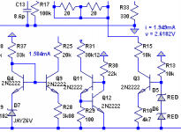
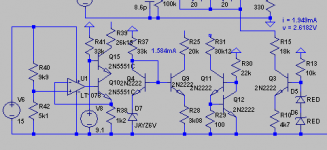
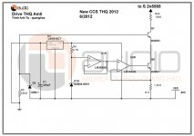
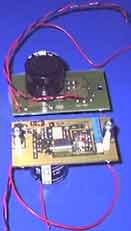
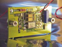
Here is my Goldmund clone (actually it doesn't have to be called a Goldmund clone just because the topology is the same) using led based ccs of 1.949mA, giving JFET source voltage of 2.6182V.
I created other 2 or 3 ccs that will give the same current and voltage, and compared them in LTSpice. To be fair, all ccs uses the same 2N2222 transistor. It is not that fair actually, because the amp has been tuned with led-based ccs in place (and the ccs itself not yet fine tuned to put the transistor in good operating condition). But anyway...
I was surprised that the led-based ccs outperform (tho microscopically) the ccs next to it. And was terribly surprised with the performance of the Goldmund Mimesis style ccs.
The Mimesis ccs gives very high distortion to the first stage. It can be seen from Goldmund amps simulation (especially Metis3) where first stage distortion is very very high. Theorists will say that it doesn't matter as long as the final distortion is fixed by feedback. I just used my voodoo skill and decided to get 0.1% distortion from the first stage
In the past I like the sound of LED-based ccs. Even now I think LED is good for sound
In the past, the listening test was conducted in an "uncontrolled" manner. But I think the real test is when led is used and it never turned us down, right?
Here is my Goldmund clone (actually it doesn't have to be called a Goldmund clone just because the topology is the same) using led based ccs of 1.949mA, giving JFET source voltage of 2.6182V.
I created other 2 or 3 ccs that will give the same current and voltage, and compared them in LTSpice. To be fair, all ccs uses the same 2N2222 transistor. It is not that fair actually, because the amp has been tuned with led-based ccs in place (and the ccs itself not yet fine tuned to put the transistor in good operating condition). But anyway...
I was surprised that the led-based ccs outperform (tho microscopically) the ccs next to it. And was terribly surprised with the performance of the Goldmund Mimesis style ccs.
The Mimesis ccs gives very high distortion to the first stage. It can be seen from Goldmund amps simulation (especially Metis3) where first stage distortion is very very high. Theorists will say that it doesn't matter as long as the final distortion is fixed by feedback. I just used my voodoo skill and decided to get 0.1% distortion from the first stage
Attachments
Here is a collection of different CCS.
It is interesting that Goldmund Mimesis ccs was not there
Today, it is strange that GIF file is not recognized by DIYAudio, so I changed to BMP, but DIYA cannot accept more than 195KB, so I changed to PNG.
better sound, frequency response is better, I find using 3 mA for each j-fet, use CCs at the most. Sounds a lot more clear!
interesting
better sound, frequency response is better, I find using 3 mA for each j-fet, use CCs at the most. Sounds a lot more clear! interesting
I believe it is mostly because you also increase the bias of the output. In my case, I want the TO-92 VAS to get no more than 500mW (and the output at no more than 400mA), without changing the already balanced characteristics of the VAS.
If you want far more higher current for the JFET you will have to change the VAS.
you can draw it?? about you say??
Attachments
Last edited:
you can draw it?? about you say??
What I mean is:
With all component values already decided, and low power transistor (e.g. TO-92) used as VAS/driver. You can change the front-end CCS to give variable current.
The higher the ccs current, the more heat VAS transistors have to dissipate. If you change the VAS transistor with bigger ones, most parameters will also be altered. It means that by changing the ccs current to certain high value, you will have to redesign your VAS and everything.
And with the same topology, I doubt you can benefit from very high current input stage (such as 14mA), but you can try. I was limited to MPSA92, 2N5401, BD139, BF470 and MJE340 for the VAS/driver (I have better parts but without model yet).
OPAMP vs LED
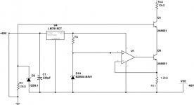
I just quickly simulated Quanghao ccs using LT opamp as shown in attachment. I tweak one resistor to output comparable current (1.949mA) and there is no improvement in distortion. In general frequency range, the opamp-based ccs has slightly lower noise. At 2kH and above the opamp wins very slightly. At bass frequency, the led-based wins. I think I prefer the led-based, unless I can tweak the opamp ccs to perform well at bass frequency.
I just quickly simulated Quanghao ccs using LT opamp as shown in attachment. I tweak one resistor to output comparable current (1.949mA) and there is no improvement in distortion. In general frequency range, the opamp-based ccs has slightly lower noise. At 2kH and above the opamp wins very slightly. At bass frequency, the led-based wins. I think I prefer the led-based, unless I can tweak the opamp ccs to perform well at bass frequency.
Attachments
I just quickly simulated Quanghao ccs using LT opamp as shown in attachment. I tweak one resistor to output comparable current (1.949mA) and there is no improvement in distortion. In general frequency range, the opamp-based ccs has slightly lower noise. At 2kH and above the opamp wins very slightly. At bass frequency, the led-based wins. I think I prefer the led-based, unless I can tweak the opamp ccs to perform well at bass frequency.
yes, i need for bass this amli!
I just quickly simulated Quanghao ccs using LT opamp as shown in attachment. I tweak one resistor to output comparable current (1.949mA) and there is no improvement in distortion. In general frequency range, the opamp-based ccs has slightly lower noise. At 2kH and above the opamp wins very slightly. At bass frequency, the led-based wins. I think I prefer the led-based, unless I can tweak the opamp ccs to perform well at bass frequency.
you can test this
thanks
Attachments
What I mean is:
With all component values already decided, and low power transistor (e.g. TO-92) used as VAS/driver. You can change the front-end CCS to give variable current.
The higher the ccs current, the more heat VAS transistors have to dissipate. If you change the VAS transistor with bigger ones, most parameters will also be altered. It means that by changing the ccs current to certain high value, you will have to redesign your VAS and everything.
And with the same topology, I doubt you can benefit from very high current input stage (such as 14mA), but you can try. I was limited to MPSA92, 2N5401, BD139, BF470 and MJE340 for the VAS/driver (I have better parts but without model yet).
this amplifier, may be i can copy?? it is one idea!
Attachments
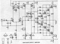
this amplifier, may be i can copy?? it is one idea!
What idea do you want to copy from that amp? It is pretty standard.
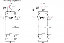
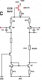
The voltage amplification, I can get A or B, C
How do you say about it!
I think balanced operation ensures linearity. So #B or #C, whichever that works.
I'm struggling to find out what will make an amp with good bass performance. From practice, amps with #C have good bass, so may be there is something in it. I'm not there yet.
I think balanced operation ensures linearity. So #B or #C, whichever that works.
I'm struggling to find out what will make an amp with good bass performance. From practice, amps with #C have good bass, so may be there is something in it. I'm not there yet.
circuitry post 37 and need a revision number will work fine, I need to do to hear them!
Thanks
An keep Opam CCS for this amli
I tried similar things with the AD797 - go toOPAM 637 is very popular with the OPA structure is simple.
I'm inspired by it and the amplifier circuit diagram has the same structure to create this amplifier 637.
This is the inner structure of OPAM
http://www.diyaudio.com/forums/soli...screte-clone-comparison-seven-variations.html
From new OP-Amps (e. g. LME series) I don't find the internal topology - go to
http://www.diyaudio.com/forums/soli...me49720-lm4562-lm-4562-lme-49710-49720-a.html
and post #26
http://www.diyaudio.com/forums/solid-state/169484-what-wrong-op-amps-3.html
nice overview.Here is a collection of different CCS.
The associated PSR curvatures I had also seen anywhere here on diyaudio before. Unfortunately I haven't save the file.
Last edited:
teifbassuebertr, I think this is the one.
i like J or CCS,
thanks
No, but nevertheless also helpful - thank you. There is an other variation found by LC technologie's "LC-Clock" in the atachment.teifbassuebertr, I think this is the one.
check out also the schematics from this german paper:
http://www.elektronik-kompendium.de/public/schaerer/curr2pol.htm
Attachments
Last edited:
No, but nevertheless also helpful - thank you. There is an other variation found by LC technologie's "LC-Clock" in the atachment.
check out also the schematics from this german paper:
Der Transistor-LED- und der FET-Konstantstromzweipol
thanks
- Status
- This old topic is closed. If you want to reopen this topic, contact a moderator using the "Report Post" button.
- Home
- Amplifiers
- Solid State
- 637 Amplifiers