I would be a little concerned regarding squares measurements from post #16, since simple LM3886 amp can do much better.
Yes I thought something about that didn't look quite right. It seems my compensation was a bit off, to say the least.
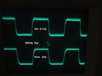
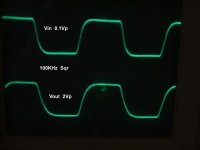
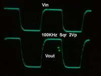
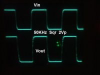
 This seems to be better, but I have to reduce the input impedance of a stage and I may be able to get it even faster. Photos show the input to the circuit on top, output on bottom. At least the 100KHz sqr doesn't look like a triangle anymore.
Attachments
OK. After a few tweaks here and a few curse words there, I think I've made some improvement. I would say it is significantly faster now than it was and may even be fast enough. It is possible that it may be operating closer to the limits of the PM than I would like, but I don't see any major stability problems jumping out at me. Will have to do some more cap tests and see...
As for the sound, it is very accurate sounding, especially WRT the highs. Cymbols and hi hat sounds crystal clear now, that little tweak made a small difference. Sufficient damping for high frequency is important to the character of any amplifier, I guess sufficient slew goes with that. I think it gives it a more transparent sound. After all, the goal in solid state is to have as little distortion products as possible due to the nature of those particular distortions. I think the closer to presenting the speaker with as close to a 'voltage source', the better off you are. Odd order harmonics and TIM have detrimental effects on sound as well. I also think that if there is any subtle phase shift between the low frequency part of the audio signal and the higher bands, it changes the way the soundstage is presented. I still can't believe how low the noise floor is, I am a bit surprised at this. I may connect my headphones directly to the output and see how much noise can be heard.
BTW did I mention those output transistors are bias at only 20 to 40mA. Typically one would bias 150 to 200mA. I wanted to push the limits of the error correction. (I can simply add a small resistor in paralell to one that is on the top of the PCB between the output transistors and increase the bias) How low can I go and still not see any crossover artifacts? Apparently about 20 to 30mA. (acutally closer to 10mA but it is always good to have some wiggle room, the gate drive signal slope gets steeper as bias approaches cut off) If this amp is operating in worse case scenario as far as bias then I think it may have promise for the future.
I would say it is significantly faster now than it was and may even be fast enough. It is possible that it may be operating closer to the limits of the PM than I would like, but I don't see any major stability problems jumping out at me. Will have to do some more cap tests and see...As for the sound, it is very accurate sounding, especially WRT the highs. Cymbols and hi hat sounds crystal clear now, that little tweak made a small difference. Sufficient damping for high frequency is important to the character of any amplifier, I guess sufficient slew goes with that. I think it gives it a more transparent sound. After all, the goal in solid state is to have as little distortion products as possible due to the nature of those particular distortions. I think the closer to presenting the speaker with as close to a 'voltage source', the better off you are. Odd order harmonics and TIM have detrimental effects on sound as well. I also think that if there is any subtle phase shift between the low frequency part of the audio signal and the higher bands, it changes the way the soundstage is presented. I still can't believe how low the noise floor is, I am a bit surprised at this. I may connect my headphones directly to the output and see how much noise can be heard.
BTW did I mention those output transistors are bias at only 20 to 40mA. Typically one would bias 150 to 200mA. I wanted to push the limits of the error correction. (I can simply add a small resistor in paralell to one that is on the top of the PCB between the output transistors and increase the bias) How low can I go and still not see any crossover artifacts? Apparently about 20 to 30mA.
(acutally closer to 10mA but it is always good to have some wiggle room, the gate drive signal slope gets steeper as bias approaches cut off) If this amp is operating in worse case scenario as far as bias then I think it may have promise for the future.Attachments
Last edited:
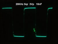
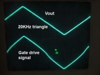
I just realized that the output bias is really set to only 15mA. It doesn't seem to affect the output signal so much but the gate drive is certainly more effected. You can see the significant change in slope in the first photo of 20KHz triangle wave ~1Ap. Since only a small part of the output is fed back to the IPS and VAS, the majority of this is the EC circuit because the VAS output looks like Vout. The gate drive signal distortion is very specific and results in a very linear output despite the type of transistors used as the output stage. Also it seems the gate drive is actually leading by just a tiny bit. The steep slope represents the high order frequency components, those you do not want to be fed back into your IPS and VAS. This just shows how much distortion these transistors create, particularly since they are bias so low. It also shows that if used properly, these so called ‘switching transistors’ become exactly the type you want to drive a reactive speaker, IMHO.
 ......Did I mention they only cost $1 each?
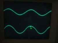
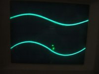
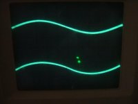
The second photo is 20KHz sine wave with the gate drive signal peak normalized to the output. (adjusted scope calibration) You can see the slope of the signal is steeper at the crossover area. The third photo is showing direct comparison of the same signal. You can see how much the change in Vgs becomes while operating at low currents due to the drop in Gm of the transistors. The last picture show the same waveform, just 2 cycles.
It doesn't seem to affect the output signal so much but the gate drive is certainly more effected. You can see the significant change in slope in the first photo of 20KHz triangle wave ~1Ap. Since only a small part of the output is fed back to the IPS and VAS, the majority of this is the EC circuit because the VAS output looks like Vout. The gate drive signal distortion is very specific and results in a very linear output despite the type of transistors used as the output stage. Also it seems the gate drive is actually leading by just a tiny bit. The steep slope represents the high order frequency components, those you do not want to be fed back into your IPS and VAS. This just shows how much distortion these transistors create, particularly since they are bias so low. It also shows that if used properly, these so called ‘switching transistors’ become exactly the type you want to drive a reactive speaker, IMHO. ......Did I mention they only cost $1 each?The second photo is 20KHz sine wave with the gate drive signal peak normalized to the output. (adjusted scope calibration) You can see the slope of the signal is steeper at the crossover area. The third photo is showing direct comparison of the same signal. You can see how much the change in Vgs becomes while operating at low currents due to the drop in Gm of the transistors. The last picture show the same waveform, just 2 cycles.
Attachments
Last edited:

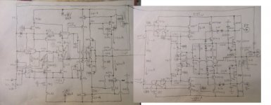
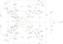
Just to show it's not all a sham, here is a basic sketch of what I have done for the amplifier circuit. Oops just noticed an error, the feedback from the output is taken before the coil not after. It is easier for me to work with a drawing on paper with pencil so I can see the whole thing all at once. It is easier to change values and get the big picture. I may get around to drawing the whole thing in a cad program.
AAhhhh J-fets!!!
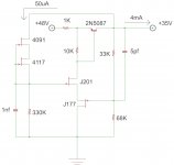
There are two of these amplifier circuits. The missing resistor values kind of depend on the J-fets. You can sort them pretty close by packaged classification but J-fets of the same type tend to have a wide variance in Gm. The +/-35V voltage source is from the regulator circuits, or DC amplifiers. This is a very quiet regulator circuit despite being fed by a half wave voltage doubler. Input Vripple~0.4V @ 60Hz. Output has excellent rejection. It uses a simple differential and VAS for the output, leading compensation. It does NOT use any God-awful noisy Zeners. The negative regulator is about the same except the Jfets are switched and the VAS is NPN. Each channel has seperate voltage regulator circuits, all just small signal stuff about 4mA each. True to my philosophy that you do not need much current until you get to the final stages.
I may get around to drawing the whole thing in a cad program.AAhhhh J-fets!!!
There are two of these amplifier circuits. The missing resistor values kind of depend on the J-fets. You can sort them pretty close by packaged classification but J-fets of the same type tend to have a wide variance in Gm. The +/-35V voltage source is from the regulator circuits, or DC amplifiers. This is a very quiet regulator circuit despite being fed by a half wave voltage doubler. Input Vripple~0.4V @ 60Hz. Output has excellent rejection. It uses a simple differential and VAS for the output, leading compensation. It does NOT use any God-awful noisy Zeners.
The negative regulator is about the same except the Jfets are switched and the VAS is NPN. Each channel has seperate voltage regulator circuits, all just small signal stuff about 4mA each. True to my philosophy that you do not need much current until you get to the final stages.Attachments
Last edited:
Hi
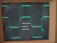
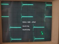
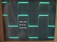
I finally got the circuit generally working properly, so it was time to re-compensate. Let me explain, when I build an amp for the first time with this many different circuits and stuff going on, I first build it with certain stages under biased. What this does is restrict the natural bandwidth of the circuit so that it is stable with little or no compensation while I poke and prod to verify that it is working properly and that I can get the same results from each channel. I find it is much easier to track down issues when the amp is slow. After it is generally working properly I increase the bias to a more suitable value and compensate accordingly. Those tiny COG caps literally cost less than a half cent each so going through several of them with a little trial and error is no issue. This amp requires certain compensation paths to be used. I now have it set up as originally designed into the PCB with about 2/3 of the 'global loop' feedback straight from the VAS output and 1/3 from the output node. Because the output follower stage is fast enough, I have included it within the Miller loop using TMC. There are also the zeros compensating the common mode amplifier. Then the EC output stage has it's own high frequency compensation, and finally the output mosfets must be locally compensated using a zero from gate to drain, with the drain having local high frequency decoupling, a 100nf small SMD film cap. This along with the gate stopper resistor will keep the mosfets from bursting out in high frequency oscillations during loading conditions. As you can see the SR is a bit faster. The 50KHz square wave looks much more square now. Next photo is 10KHz with 470nf Mylar film cap. Third is 100KHz square wave, Av is now set to 35. Gain with a sine wave is flat from 16Hz with the high end -3dB gain about 350KHz. The amp clips at 24V so 0.68Vp input signal will clip the amp, at which point the green LED flashes red to indicate the clipping. I think this complete Hi-Fi amplifier module has promise, the sound is quite excellent now! Sometimes things are complex just to be complex. The design goal of this amp is to accomplish a goal regardless of how many parts it took, few compromises. I quite surprised myself this time. All the parts contribute in some way to the ends, so the ends justified the means. It's getting closer now.....
I finally got the circuit generally working properly, so it was time to re-compensate. Let me explain, when I build an amp for the first time with this many different circuits and stuff going on, I first build it with certain stages under biased. What this does is restrict the natural bandwidth of the circuit so that it is stable with little or no compensation while I poke and prod to verify that it is working properly and that I can get the same results from each channel. I find it is much easier to track down issues when the amp is slow. After it is generally working properly I increase the bias to a more suitable value and compensate accordingly. Those tiny COG caps literally cost less than a half cent each so going through several of them with a little trial and error is no issue. This amp requires certain compensation paths to be used. I now have it set up as originally designed into the PCB with about 2/3 of the 'global loop' feedback straight from the VAS output and 1/3 from the output node. Because the output follower stage is fast enough, I have included it within the Miller loop using TMC. There are also the zeros compensating the common mode amplifier. Then the EC output stage has it's own high frequency compensation, and finally the output mosfets must be locally compensated using a zero from gate to drain, with the drain having local high frequency decoupling, a 100nf small SMD film cap. This along with the gate stopper resistor will keep the mosfets from bursting out in high frequency oscillations during loading conditions. As you can see the SR is a bit faster. The 50KHz square wave looks much more square now. Next photo is 10KHz with 470nf Mylar film cap. Third is 100KHz square wave, Av is now set to 35. Gain with a sine wave is flat from 16Hz with the high end -3dB gain about 350KHz. The amp clips at 24V so 0.68Vp input signal will clip the amp, at which point the green LED flashes red to indicate the clipping.
I think this complete Hi-Fi amplifier module has promise, the sound is quite excellent now! Sometimes things are complex just to be complex. The design goal of this amp is to accomplish a goal regardless of how many parts it took, few compromises. I quite surprised myself this time. All the parts contribute in some way to the ends, so the ends justified the means. It's getting closer now.....Attachments
Last edited:
I need to track down a spectrum analyzer to get a more accurate picture, O-scope can only show you so much. I may know someone who can get access to one, I would like to see any difference between having the output transistors at low bias (30mA) compared to a more proper bias >100mA. I also want to measure the noise spectrum. The fact that I have to press my ear into the tweeter just to hear any white noise is a good sign.
I may know someone who can get access to one, I would like to see any difference between having the output transistors at low bias (30mA) compared to a more proper bias >100mA. I also want to measure the noise spectrum. The fact that I have to press my ear into the tweeter just to hear any white noise is a good sign.Another version of home brew...
Although I am a member of a "twelve step program" for a number of years, I highly recommend just plain home brewing.
This is particularly true if you live in Western Europe and/or other areas where alcohol is taxed ridiculously as if we are not supposed to drink it in huge quantity.
Even here in America, the land of low taxes and borrowing as much as we can from gullible foreigners until the bottom falls out, those who like malt beverages know that, while you can get reasonably good beers at last, the old Monty Python joke is still very apt:

Q: "How is American beer like making love in a canoe?"
A: "It's f*****g close to water!" [I'm not allowed to say the second word, but it rhymes with "Trucking". I'm sure you can figure it out!]
Although I am a member of a "twelve step program" for a number of years, I highly recommend just plain home brewing.
This is particularly true if you live in
Western Europe and/or other areas where alcohol is taxed ridiculously as if we are not supposed to drink it in huge quantity. Even here in America, the land of low taxes and borrowing as much as we can from gullible foreigners until the bottom falls out, those who like malt beverages know that, while you can get reasonably good beers at last, the old Monty Python joke is still very apt:
Q: "How is American beer like making love in a canoe?"
A: "It's f*****g close to water!" [I'm not allowed to say the second word, but it rhymes with "Trucking". I'm sure you can figure it out!]
And for some it is worse. In Tenn, the beer taxes are based on wholesale supply not price. Couple that with licensing here and it means you can't get a really good beer. It varies from state to state but here you have a beer license that allows you to sell up to 6% alc/vol. Then there is a seperate wine and liquor license. Although this may change next year as current legislation may allow, it is not as bad as some places like Colorado or Utah with the 3.2 beer crap. At least in FL you have more choices.
Couple that with licensing here and it means you can't get a really good beer. It varies from state to state but here you have a beer license that allows you to sell up to 6% alc/vol. Then there is a seperate wine and liquor license. Although this may change next year as current legislation may allow, it is not as bad as some places like Colorado or Utah with the 3.2 beer crap. At least in FL you have more choices.Vertical Mosfet distortion.........
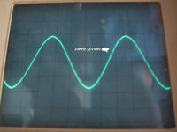
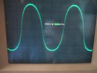
How much distortion do vertical output fets and particularly planer stripe fets create when only bias at 30mA? I would say it is quite significant. With my 6R nom, 4-way speaker cabinate connected to the amp, I input a 20KHz sine wave from my function generator. It's kind of a cheapie and has a very fine notch at the top and bottom of the waveform. It's neat that this is also amplified. First photo is the output signal. The second photo shows the difference between the output and the signal at the gate, this is the error correction signal. It certainly doesn't look like a sine wave but rather is a complex polynomial function containing specific high frequency information that corresponds to the non-linear nature of the sum of Gm from both output mosfets as the current signal travels through the zero crossing. Notice the asymetrical nature of the error correction signal between turn on and turn off of each mosfet. Also the EC signal leads just a tiny bit, which makes sense because the speaker should present a more capacitive load at 20KHz. I think it is pretty neat that I can get such linearity from such cheap non-linear devices and still have just 1.5W idle power per pair. ....
Oh...but those are switching transistors many will say, then I will say so what?
How much distortion do vertical output fets and particularly planer stripe fets create when only bias at 30mA? I would say it is quite significant.
With my 6R nom, 4-way speaker cabinate connected to the amp, I input a 20KHz sine wave from my function generator. It's kind of a cheapie and has a very fine notch at the top and bottom of the waveform. It's neat that this is also amplified. First photo is the output signal. The second photo shows the difference between the output and the signal at the gate, this is the error correction signal. It certainly doesn't look like a sine wave but rather is a complex polynomial function containing specific high frequency information that corresponds to the non-linear nature of the sum of Gm from both output mosfets as the current signal travels through the zero crossing. Notice the asymetrical nature of the error correction signal between turn on and turn off of each mosfet. Also the EC signal leads just a tiny bit, which makes sense because the speaker should present a more capacitive load at 20KHz. I think it is pretty neat that I can get such linearity from such cheap non-linear devices and still have just 1.5W idle power per pair. ....Oh...but those are switching transistors many will say, then I will say so what?
Attachments
Last edited:
Hi
I have noticed that the typical vertical type mosfet used by most folks tend to be Hexfets. In this amp I have used a different type of vertical mosfet particularly Q-fets from Fairchild. I started playing with these just out of curiosity, but then I discovered some hidden potential, other than the intended switching purposes. They don’t seem to be very popular with the exception of Mr. Pass using them for class A amplifiers. When comparing the transfer of the Planer Stripe fets, or ‘Q-fet’ to that of a conventional Hexfet there seems to be a significant difference if one plans to use them class AB. See figure 1 in the datasheet for FQP30N06, and compare it to figure 1 in the datasheet for the IRFZ34, a Hexfet similar in Gm and Vds breakdown to the FQP30N06. Although all mosfets suffer from a drop in Gm at lower drain currents, it appears that within this region there is a stronger correlation between Gm and Vds in the Planer Stripe fets. Generally speaking, not even Trench fets show this strong correlation. I found a couple papers that can better explain some of the physical architecture differences, at least the first couple pages. The rest is related to switching performances. I suppose the dependence of Gm on Vds is an effect of the different shape of the P-well structure. Gate charge vs di/dt is smaller. It does appear that the channel density of the Planer Stripe is higher.
I have noticed that the typical vertical type mosfet used by most folks tend to be Hexfets. In this amp I have used a different type of vertical mosfet particularly Q-fets from Fairchild. I started playing with these just out of curiosity, but then I discovered some hidden potential, other than the intended switching purposes. They don’t seem to be very popular with the exception of Mr. Pass using them for class A amplifiers. When comparing the transfer of the Planer Stripe fets, or ‘Q-fet’ to that of a conventional Hexfet there seems to be a significant difference if one plans to use them class AB. See figure 1 in the datasheet for FQP30N06, and compare it to figure 1 in the datasheet for the IRFZ34, a Hexfet similar in Gm and Vds breakdown to the FQP30N06. Although all mosfets suffer from a drop in Gm at lower drain currents, it appears that within this region there is a stronger correlation between Gm and Vds in the Planer Stripe fets. Generally speaking, not even Trench fets show this strong correlation. I found a couple papers that can better explain some of the physical architecture differences, at least the first couple pages. The rest is related to switching performances. I suppose the dependence of Gm on Vds is an effect of the different shape of the P-well structure. Gate charge vs di/dt is smaller. It does appear that the channel density of the Planer Stripe is higher.
Attachments
update.......
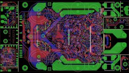
I have decided to revisit this project. It has been awhile since I've done anything with this project (except listen to music, this is the amp I still use almost every day from post 17........over 2 years and no real issues. ) Time to move on with the new updated version. PCB is almost ready, just some minor drawing adjustments and a final QC and check of the nomenclature for the silk screen layers. I did not redraw the PCB but just changed and added some things. There are some changes in the construction and mounting of things but this is why we build protos, no? The cutaway pieces are a bit different and I plan to use a THAT2162 chip for the input volume control.
When completed it will be a complete stereo system with power supply and all control logic, thermal management, circuit protections, and a single potentiometer to control volume of both channels all on 1 PCB. Only other items required is a power transformer, enclosure, and binding posts for I/O.
I have decided to revisit this project. It has been awhile since I've done anything with this project (except listen to music, this is the amp I still use almost every day from post 17........over 2 years and no real issues.
) Time to move on with the new updated version. PCB is almost ready, just some minor drawing adjustments and a final QC and check of the nomenclature for the silk screen layers. I did not redraw the PCB but just changed and added some things. There are some changes in the construction and mounting of things but this is why we build protos, no? The cutaway pieces are a bit different and I plan to use a THAT2162 chip for the input volume control. When completed it will be a complete stereo system with power supply and all control logic, thermal management, circuit protections, and a single potentiometer to control volume of both channels all on 1 PCB. Only other items required is a power transformer, enclosure, and binding posts for I/O.
Attachments


And for some it is worse. In Tenn, the beer taxes are based on wholesale supply not price.
Have yer' cheap beer. Across the valley here ,Sevier county serves up 12% beer and
either 100 or even 150 proof moonshine.
The hypocrites passed all these "ordinances" in just 3 years. Went from almost a "dry" county to a "freeforall" ??? (worse than NY).
PS - they won't let the national brand "ghetto beers" in here , but >6% microbrewery product is alright ... mo' $$$$ (tourists / hypocrites).
OS
PCB is about ready. Got a promotion offer, hopefully might save a few bucks......
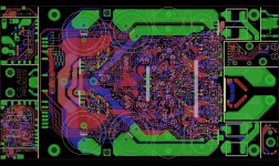
anyway, if it works like the predecessor, it will be more than worth it. The last one used 0201 resistors, works just fine. But, they are a pain to assemble. The % of board space saved by them is miniscule compared to 0402. Much easier to assemble. Plus, they seem to be cheaper. In this version I was able to re-route so as to be able to convert many of the single 0402 resistors into 2X0603 arrays, greatly reducing component count. Uh huh, I know it doesn't look like much of a component count reduction, but after all, it is an entire stereo system with several interconnected "circuits" crammed onto a 4.5" X 7.5" PCB, minus the power transformer and enclosure, complete with redundant protection circuitry and clipping indication.
anyway, if it works like the predecessor, it will be more than worth it.
The last one used 0201 resistors, works just fine. But, they are a pain to assemble. The % of board space saved by them is miniscule compared to 0402. Much easier to assemble. Plus, they seem to be cheaper. In this version I was able to re-route so as to be able to convert many of the single 0402 resistors into 2X0603 arrays, greatly reducing component count. Uh huh, I know it doesn't look like much of a component count reduction, but after all, it is an entire stereo system with several interconnected "circuits" crammed onto a 4.5" X 7.5" PCB, minus the power transformer and enclosure, complete with redundant protection circuitry and clipping indication.Attachments


- Status
- This old topic is closed. If you want to reopen this topic, contact a moderator using the "Report Post" button.
- Home
- Amplifiers
- Solid State
- New home brew amp module