Thanks ostripper. One more question but not a mainstream one. Got my boards on Friday so I started to study more carefully the design.
Why such high resistor values in led circuits? I must be missing something. The formula I'm using for such resistors is: R = (VS-Vled)/Iled. Diodes from my supplier have Vled about 2.1V for red and 2.6V or 3.5V for blue. Iled is usually 20mA (but there are also small 2mA diodes). 20mA gives me resistor value of about 3.3k for red with VS=63V (rail to the ground). It does not have to burn brightly but you have 22k for red and 100k for blue. Could you please explain?
cheers,
Modern led's are way too bright for basic indication purposes. Blue's and whites can be bright enough with 220k+.
An old E-waste red from the 70's (Ga-As) may just need 10-20ma to be seen. A modern red with more advanced materials is 10-20+ times the efficiency and will be a good (better) indicator at 1-2ma. The first Badgers ..(frugalamp) used a red led CCS and surprisingly , with a 22k dropping resistor value , the red was typical in brightness AND was a good current source.
The 22k and 100k values have been tested from 40-60V rails and perform their job of basic indication well. 150K would even be better for some blue's !!
BTW - the purpose of these led's is to show that you have potentially lethal voltages present - especially with some of the monster PS's I see in the builds.
OS
Could someone confirm my signal wiring diagram? I'm not sure if I need to connect the spkr grnd pads on the badger boards to the star, it seems they already are via the board traces but I saw some other badger builds where the person had made that ground connection.
Attachments
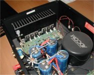
Perhaps Andrew T. could clarify .... but look at the ADCOM's -
photo 1 = single bridge/single trafo.
Speakers both go to single central star.
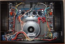
Photo 2 = dual bridge/single trafo.
Speakers go to separate L-R star's.
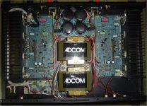
Photo 3= dual mono/dual trafo
Speakers also go to separate L-R star's.
The only difference with the badger is the fact it has onboard supply caps. the Adcom leaves this feature out and even sends the zoble return back to the offboard star on small black wires (all 3 photo's).
The answer would depend on what PS setup you have.
PS - those adcom's (535/45/55) were designed by Nelson Pass !! wow...
EDIT - even for scenario 1 (single) the "SPK" terminal would act as just one return to the star.
OS
photo 1 = single bridge/single trafo.
Speakers both go to single central star.
Photo 2 = dual bridge/single trafo.
Speakers go to separate L-R star's.
Photo 3= dual mono/dual trafo
Speakers also go to separate L-R star's.
The only difference with the badger is the fact it has onboard supply caps. the Adcom leaves this feature out and even sends the zoble return back to the offboard star on small black wires (all 3 photo's).
The answer would depend on what PS setup you have.
PS - those adcom's (535/45/55) were designed by Nelson Pass !! wow...
EDIT - even for scenario 1 (single) the "SPK" terminal would act as just one return to the star.
OS
Attachments
Last edited:
I'm using the v3 diyAudio PS boards: two split-rail boards, two transfos. Andrew replied in this post but I'm not sure if he was referring to the same thing I'm talking about.
http://www.diyaudio.com/forums/soli...honey-badger-build-thread-53.html#post3616499
http://www.diyaudio.com/forums/soli...honey-badger-build-thread-53.html#post3616499
The problem I see is that you don't show the supply ground. Typically you take the supply ground, grounds from each PCB and speaker grounds to the same point, a star ground. I got in the habit of tying the input grounds together at the input sockets and then just taking one ground to the board. I've never gotten a ground loop following those rules. I'm sure others will have a different outlook on that.
The problem I see is that you don't show the supply ground. Typically you take the supply ground, grounds from each PCB and speaker grounds to the same point, a star ground.
Like this? (attachment) I will be attaching the IEC ground to the chassis.
I got in the habit of tying the input grounds together at the input sockets and then just taking one ground to the board. I've never gotten a ground loop following those rules. I'm sure others will have a different outlook on that.
With dual mono though?
Attachments
Bob suggested lifting the ground in this thread http://www.diyaudio.com/forums/soli...honey-badger-build-thread-50.html#post3609426. Does that accomplish the same thing?
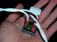
Ground loop breaker photo attached.
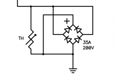
The bridge rectifier and cap are typical. However, there are many possibilities of resistor to use, such as thermal resistor for a more effective disconnect or a wirewound for high surge tolerance. The resistor is usually chosen specific to a design.
Rectifier schottky does not work here because it would switch too much--The diodes are a standard silicon type (ordinary) set anti-parallel, giving approximately 0.7v drop in both/every directions. If the ground loop exceeds approximately 0.65 volts, this device will switch on and conduct. It may be informative to measure the voltage across before installing the resistor.
Attachments
Last edited:
post549 shows two wires IN and two wires OUT.
That does not look like a normal implementation of a ground loop breaker (or Disconnecting Network)
A Main Audio Ground to Chassis safety connection is a ONE WIRE connection.
It can be either a direct copper wire connection, or it can have a Disconnecting Network in that ONE WIRE connection.
I have never seen a TWO WIRE Disconnecting Network.
Why on our Earth do we need a Power resistor. How much power can it dissipate when a 1kA Fault Current passes through the Disconnecting Network to the PE protected Chassis?
I'll show you an approximation of how much power.
Vf peak when passing 1kA through a pair of paralleled 25A or 35A power rectifier diodes can be around 1V to 2V.
Allowing the higher estimate of 2V the instantaneous peak dissipation (until the mains fuse blows) is 2V*2V/10r = 400mW for <0.1ms.
Any 250mW or 400mW or 600mW metal film resistor will easily survive this peak dissipation.
Even if the resistor were to fail the Disconnecting Network is still perfectly capable of passing the next 1kA Fault Current to the PE protected Chassis.
Which post?Bob suggested lifting the ground in this thread http://www.diyaudio.com/forums/soli...honey-badger-build-thread-50.html#post3609426. Does that accomplish the same thing?
post549 shows two wires IN and two wires OUT.
That does not look like a normal implementation of a ground loop breaker (or Disconnecting Network)
A Main Audio Ground to Chassis safety connection is a ONE WIRE connection.
It can be either a direct copper wire connection, or it can have a Disconnecting Network in that ONE WIRE connection.
I have never seen a TWO WIRE Disconnecting Network.
Why on our Earth do we need a Power resistor. How much power can it dissipate when a 1kA Fault Current passes through the Disconnecting Network to the PE protected Chassis?
I'll show you an approximation of how much power.
Vf peak when passing 1kA through a pair of paralleled 25A or 35A power rectifier diodes can be around 1V to 2V.
Allowing the higher estimate of 2V the instantaneous peak dissipation (until the mains fuse blows) is 2V*2V/10r = 400mW for <0.1ms.
Any 250mW or 400mW or 600mW metal film resistor will easily survive this peak dissipation.
Even if the resistor were to fail the Disconnecting Network is still perfectly capable of passing the next 1kA Fault Current to the PE protected Chassis.
i bet the twisted pair wires are conected together.
Is this one that I lifted from Pass what you were referring to, Matt?
Yes.
Be sure that the IEC ground connects directly to the case rather close to the inlet. The system ground can then connect to the case someplace convenient.
You might also consider lifting the system ground with a 35A bridge and CL60 like Nelson Pass does in many of his designs. This arrangement would go between the star and the case.
Don't the amp boards have a ground connection? AKA 0V - connect that to the star.
You can connect the purple wires on the big toriods to ground. It connects to the shield and should give you a bit better noise performance when connected to ground.
This was the post I was referring to as well.
What is the purpose of the bridge?You might also consider lifting the system ground with a 35A bridge and CL60 like Nelson Pass does in many of his designs. This arrangement would go between the star and the case.
This was the post I was referring to as well.
thats the same as i posted in post 547
")
What is the purpose of the bridge?
the purpose is to lift(seperate chassis ground/ audio grounds untill it cunducts. and only then conect audio grounds to chassis ground.
Do you use it in all your amps? I've always felt that having the ground connected to the case made the case into a sort of ground shield which would help shield against outside interference. Why is this a bad thing?the purpose is to lift(seperate chassis ground/ audio grounds untill it cunducts. and only then conect audio grounds to chassis ground.
Thanks
- Home
- Amplifiers
- Solid State
- diyAB Amp The "Honey Badger" build thread