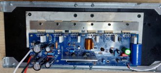
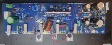
The grey plate between the transistors and the heatsink is an 8mm thick pure copper plate, with chemical tinning. To hold the transistors, it is a 3 x 20 mm pure copper bar with chemical tinning. I wanted the temperature to be as homogeneous as possible. Copper is the way to go. On the other hand, it weighs heavily.

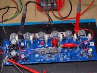
Here is a fresh right channel.You need to instal all parts except the output power transistors .
Omit R36 ,connect the output to each driver emitter using resistors 68 Ohm .
This way you ended up with a small 5 W amplifier
If it is a sassesfull atempt,as Pete recommended you have to remove the resistors from the output,install the R36 and the output trsnsistors.
This way (low current consumption)you haven't to worry for a catastrophic and expensive failure .
I have set it up for the 5W amp test.
During the first quick on-off test I will look for working LEDs and close to 0V on the 10R resistors.
I will use the dim bulb.
Have I set this up correctly?
If this works, in the second round I will power up and measure for:
DC offset @ 1-2mV
8.25V across R14
Use R30 to bias to 15-20mV
If that all works in 3rd round, I will remove the 10R resistors. Install the R36 resistor and fuses.
Then finish biasing by targeting 20mV -25mV between TP1 and TP2.
Attachments
Ok. Got that. Went back to OS input where he said driver emitters should read 1.1-1.2V -(between them) adjust Vbias [5289]. So I get this reading across one or both of the 68R resistors. Is that correct?
Assuming everything is good, shut down, put in R36 and the fuses and the output transistors to finalize Bias. Also remove 10R resistors.
Assuming everything is good, shut down, put in R36 and the fuses and the output transistors to finalize Bias. Also remove 10R resistors.
Across Both. NPN is typically .53V BE PNP is a little less (.5 'ish) . I have some older Panasonic outputs that are .49V.
Combine 2 Re's (N/P) = 1V or a little more.
Put the outputs in and you will be right at conduction , offset might jump around slightly. As you exceed .5xx (one device) - both outputs
conduct , offset should settle. 22mV would equal 100Ma .
I have seen amps not settle offset , they oscillate. Fortunately , Badger does not - unless you forget the miller (TMC) Cap(s).
Edit - final bias ... 100Ma-22mV is OK. simulation and real world test show 70mA is the sweet spot for lowest THD. I bias to
15mV for my output stages. Sankens tend to be good down to <50mA. Different junction wafer characteristics ??
OS
Last edited:
Thanks, OS, for the help here. As this is my third try, I'm a little gun shy.
As shown below, is this the correct way to read across Q14 & Q15?
Is the ~1V reading across them in addition to the bias readings:
R7 = 8.25V
R17 = > 0.5V
R30 = 15-20mV
Or an alternate way to get there?
I assume for initial test I'm still looking for .0 across the 10R resistor and LEDs turn on.
As shown below, is this the correct way to read across Q14 & Q15?
Is the ~1V reading across them in addition to the bias readings:
R7 = 8.25V
R17 = > 0.5V
R30 = 15-20mV
Or an alternate way to get there?
I assume for initial test I'm still looking for .0 across the 10R resistor and LEDs turn on.
Attachments
Hello Forum Members,
I believe I may have overcome the initial hurdle on channel A of my HB board.
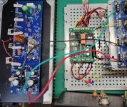
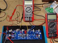
I set up the 5W amp test as described by OS. I slowly brought up my voltage using a variac and dim bulb tester. See photo.
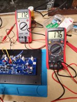
I have two bright, steady LED's. No smoke. DC voltage accross the 10ohm resisters that I used instead of fuses was less than 0.2 volts. See photo.
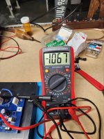
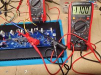
DC voltage reading between the two driver emitters was 1.06 volts. See photo.
I think this is a good sign? Power was on about 1-2 minutes without any apparent issues. Is there anything I may have missed that I'm not aware of?
I am waiting for more Keratherm insulators to arrive so I can test channel B and install the outputs. Thank you.
Dave M.
I believe I may have overcome the initial hurdle on channel A of my HB board.
I set up the 5W amp test as described by OS. I slowly brought up my voltage using a variac and dim bulb tester. See photo.
I have two bright, steady LED's. No smoke. DC voltage accross the 10ohm resisters that I used instead of fuses was less than 0.2 volts. See photo.
DC voltage reading between the two driver emitters was 1.06 volts. See photo.
I think this is a good sign? Power was on about 1-2 minutes without any apparent issues. Is there anything I may have missed that I'm not aware of?
I am waiting for more Keratherm insulators to arrive so I can test channel B and install the outputs. Thank you.
Dave M.
Attachments
Amp will still use power without the outputs. Input stage uses 12-15 ma per rail + the led currents , .1-.2V or so across the 10R's.I assume for initial test I'm still looking for .0 across the 10R resistor and LEDs turn on.
OS
Hello Sir,
On my Badger, I replaced the input capacitor, a 4.7μF polypropylene Epcos with a 10μF Mundorf Evo Oil.
The difference is very noticeable.
The soundstage is wider, the piano is thinner, the guitar and double bass strings never stop vibrating.
It's pure bliss.
I invite you to give it a try, if you have some space in your case.
Alain
Hello Forum Members,
I believe I have successfully used the 5W amp setup to test channel B of my HB build.
Same setup. DC voltage accross the two 10 ohm safety resistors was less than 0.2v. Initially offset between the two driver emitters was initially upwards of 1.9VDC. I had to crank on the trimmer quite a ways to bring the offset down to 1.1VDC. I hope this is not indicative of an underlying issue.
Again, like my first board I had two bright, steady LED's with no smoke. Power was on 2-3 minutes with no apparent issues.
Unless something changes, I'll begin installing the outputs to prepare for further testing and adjustment. Thanks for following. Dave M.
Attachments
Hello Forum Members,
A couple of questions for anyone who may feel inclined to offer feedback.
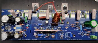
I installed the output transistors on board B of my HB. With 10 ohm safety resistors installed I adjusted R17 to its smallest reading. I was only able to get DC offset down to 4 mV if I was reading my DMM correctly. Is this a concern?
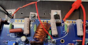
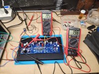
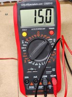
I placed my DMM probes in TP1 and TP2 and adjusted R30 until I had 15 mV. (If I'm reading the scale correctly) See pic.
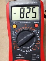
As I increased this setting the reading accross my 10 ohm safety resistor increased to 0.825 VDC. (See pic) Is this to be expected?
At this point I powered down. I think I'm on the right track but need time to think this through. Both LED's lit bright and steady. Power was on 4-5 minutes and nothing smelled hot. No smoke. Any concerns that forum members can identify before I continue? I'm cautiously optimistic. Thanks. Dave M.
A couple of questions for anyone who may feel inclined to offer feedback.
I installed the output transistors on board B of my HB. With 10 ohm safety resistors installed I adjusted R17 to its smallest reading. I was only able to get DC offset down to 4 mV if I was reading my DMM correctly. Is this a concern?
I placed my DMM probes in TP1 and TP2 and adjusted R30 until I had 15 mV. (If I'm reading the scale correctly) See pic.
As I increased this setting the reading accross my 10 ohm safety resistor increased to 0.825 VDC. (See pic) Is this to be expected?
At this point I powered down. I think I'm on the right track but need time to think this through. Both LED's lit bright and steady. Power was on 4-5 minutes and nothing smelled hot. No smoke. Any concerns that forum members can identify before I continue? I'm cautiously optimistic. Thanks. Dave M.
Attachments
It sounds like the amp is working correctly. Once the amp is warmed up and burned in you can try readjusting the DC offset but it will likely wander around a bit because the amp doesn't have a servo. .825V across the 10 ohm resistors means you are passing around 85mA of current, which sounds fine.
@UncleMud
Your readings look good. 4mV DC offset at this stage is fine (in fact, it’s fine in the final settings as well). You are biased low with just 34mA across each set of output transistors (there are 3 ”pairs”), so in total that is 34mA *3 = 102mA. The 10 ohm safety resistor (on one rail) is reading 85mA of current which would be right (the 10 ohm resistor is measuring the overall current draw of the entire circuit including the input/driver stages) …time to remove those resistors and install fuses, then advance your bias so TP1 and TP2 measure about 44mv as the guide suggests. I bet you’ll be able to adjust the DC offset close to 0mV once thermal equilibrium and final bias settings are set.
Keep going!
Best,
Anand.
Edit…jwilhelm already replied!
Last edited:
Thanks for the feedback @poseidonsvoice. Always good to hear your thoughts. I appreciate your time.
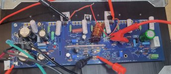
New board.
First test.
R36 out.
5W amp setup
10R in place
Wiring: amp to DBT to Variac.
I ran the Variac up to 60V AC
LED lights on
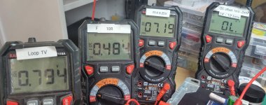
These are the readings:
10R: -0.484 DCV
R14: 07.19 DCV
Q 14 & Q15 Loop: 0.794 DCV
Offset: OL
Am I on the right track?
Thanks,
First test.
R36 out.
5W amp setup
10R in place
Wiring: amp to DBT to Variac.
I ran the Variac up to 60V AC
LED lights on
These are the readings:
10R: -0.484 DCV
R14: 07.19 DCV
Q 14 & Q15 Loop: 0.794 DCV
Offset: OL
Am I on the right track?
Thanks,
Attachments
- Home
- Amplifiers
- Solid State
- diyAB Amp The "Honey Badger" build thread