Before I start turning the lights on, do I have the grounding scheme correct? I seemed to be confused about this.Ok. First things first. Regarding the correct PSU wiring to amp board.
Have I sorted this correctly?
Thanks
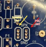
From where the "spk" is marked I'd think that's where the speaker ground should be connected?
Thanks
Attachments
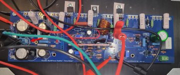
Well, things didn't go as planned. I built my 2nd board and set things up for initial test. But I had messed up and ran the PSU ground to the speaker ground. On turn on, with DBT, I saw smoke immediately. I turned the amp off. I tested all the resistors and could not detect what had smoked.
So I set up for initial test again with the PSU ground to ground {as shown above} and turned it on. Again smoke. Turned it off. Cannot see any visible source of smoke. Not sure what is going on. Did I fry something in the first round that doomed the 2nd turn on? Or is some part in the wrong place.
I'm inclined to build another board and hope that third time is the charm.
So I set up for initial test again with the PSU ground to ground {as shown above} and turned it on. Again smoke. Turned it off. Cannot see any visible source of smoke. Not sure what is going on. Did I fry something in the first round that doomed the 2nd turn on? Or is some part
I'm inclined to build another board and hope that third time is the charm.
Attachments
I see a red connector attached to the -ve terminal.
Smoke is likely the limiting resistors across the fuse.
(edit) I think the red connector is for measuring.
The 3A power diodes saved my amp when I got mixed-up with the colours of the power supply wires, thinking you may have made the same mistake I did.
Smoke is likely the limiting resistors across the fuse.
(edit) I think the red connector is for measuring.
The 3A power diodes saved my amp when I got mixed-up with the colours of the power supply wires, thinking you may have made the same mistake I did.
Last edited:
The ground connections both connect to the exact same place, so they won't matter which one you connect the supply to.
A picture of your amp board and supply might help in figuring out your issues. As Johnnyx suggests, it sounds like you have something connected wrong.
A picture of your amp board and supply might help in figuring out your issues. As Johnnyx suggests, it sounds like you have something connected wrong.

Chiptech,
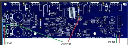
To convince yourself of this, note the circuit trace drawing/foil trace in the design doc which I am assuming you have and probably have memorized by now:

Note how speaker ground and power ground are exactly in the same place. Electrically they are the same.
I am very curious as to what was connected to the RED alligator clip which is attached to your speaker output section. That should be connected to a DMM. The COM section of your DMM should be connected to one of the GND terminals.
Your V+/V- should be connected to your power supply, it’s hard to see that in your pic. And obviously there needs to be a ground reference, so your PS ground should be connected to GND as well.
Do you have a variac? Or a bench supply? Or do you only have a dim bulb tester (DBT)?
Best,
Anand.
To convince yourself of this, note the circuit trace drawing/foil trace in the design doc which I am assuming you have and probably have memorized by now:
Note how speaker ground and power ground are exactly in the same place. Electrically they are the same.
I am very curious as to what was connected to the RED alligator clip which is attached to your speaker output section. That should be connected to a DMM. The COM section of your DMM should be connected to one of the GND terminals.
Your V+/V- should be connected to your power supply, it’s hard to see that in your pic. And obviously there needs to be a ground reference, so your PS ground should be connected to GND as well.
Do you have a variac? Or a bench supply? Or do you only have a dim bulb tester (DBT)?
Best,
Anand.
Double check the drivers (MJEs on h/s) are in the correct position, not swapped? Can't tell from your picture. Also, are your VAS on the small aluminum h/s properly isolated, again can't tell exactly which transistors you are using, but I don't see insulators on h/s or bolts.
Thanks for all the input.
1. Ground doesn't matter which the PSU ground goes to. Got it.
2. It's entirely possible that I switched the + / - leads from the PSU to the amp board. I thought I checked that, but now I can't be sure.
3. I forgot to use the insulators and did not use thermal cote on the heat sink transistors or on the two sets of transistors. So that has to be sorted.
4. I did use a DBT and did not see the bulb dimmed quickly and then I smelled smoke. I have a variac. I don't have a bench supply but could likely borrow one for the next round.
More to come.
So you don't waste any more outputs , I omit R36 .... run 2 -68R resistors from Q14/15 driver emitters to the output. driver emitters should read 1.1-1.2V -(between them) adjust Vbias .... Then populate the "big boys" NJW's ...
What you are doing here is creating a little 5W amp with the drivers BEFORE you put the high current parts in. You don't even have to heatsink Q14/15 to
pretest for high power. 1.1V will equate to very low (bias) current with the installed outputs.
OS
What you are doing here is creating a little 5W amp with the drivers BEFORE you put the high current parts in. You don't even have to heatsink Q14/15 to
pretest for high power. 1.1V will equate to very low (bias) current with the installed outputs.
OS
You need to instal all parts except the output power transistors .
Omit R36 ,connect the output to each driver emitter using resistors 68 Ohm .
This way you ended up with a small 5 W amplifier
If it is a sassesfull atempt,as Pete recommended you have to remove the resistors from the output,install the R36 and the output trsnsistors.
This way (low current consumption)you haven't to worry for a catastrophic and expensive failure .
Last edited:
Hello Forum Members,
I have been following Chip's start-up efforts as I am about two weeks from testing my boards.
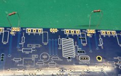
Please forgive my confusion. The recommendation from Pete and thimios to omit R36, and connect the emitters of Q14/15 to the output using 68ohm resisters sounds like a great strategy. I would like to try this myself. Could someone review the picture I have attached to see if I am understanding correctly? I have drawn a red line where I think the connections should be. Thank you for your patience.
Respectfully,
Dave M.
I have been following Chip's start-up efforts as I am about two weeks from testing my boards.
Please forgive my confusion. The recommendation from Pete and thimios to omit R36, and connect the emitters of Q14/15 to the output using 68ohm resisters sounds like a great strategy. I would like to try this myself. Could someone review the picture I have attached to see if I am understanding correctly? I have drawn a red line where I think the connections should be. Thank you for your patience.
Respectfully,
Dave M.
Attachments
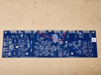
Yes , perfect... drivers don't even have to be heatsinked. Little 5W amp dissipates <20mA. I've even hooked headphones to a pairI have drawn a red line where I think the connections should be.
of amps like this through a 33R resistor.
Edit - while I've checked/adjusted the current sources . Offset needs the outputs for a final adjustment. Bias at 1V between emitters.
OS
Last edited:
Hi everyone,
I built two Badger amps with the PCBs from DiyAudio shop and this forum.
Thank you to the designer and everyone who contributed ideas.
I made some edits with the help of MicroCaps12. I wanted a higher quiescent current (200mA for each transistor : 88mV between TP1/TP2). So I lowered the supply voltage to 30V instead of 55V.
I kept the current into R14 at 3.75mA.
R23 = R27 = 47 ohms . The current across R27 is 12,5mA.
I replace SA1381 and SC3503 by TTA/TTC004 because I hab them in stock.
The drivers are MJE150345/35 and the output transistors are MJL4302A/MJL4281A. The 150ohm R36 resistor is divided into two 75ohm resistors and the midpoint is connected to the midpoint of the 0.22ohm resistors.
C7 = 68pF and R15-16 = 47ohms instead of 100ohms.
With the values of the forum, the amp worked the first time. I did the evolutions afterwards.
I really like the result.
The amp is very stable. The heatsinks are around 40°C. It takes 20 minutes of heating.
The cold output drift is about 12mV and hot is a few millivolts.
The power supply are SMPS 300RE model with CLC filter between SMPS and amplifier. (660µF - 10µH - 10000µF)
The next modification will be to put before the amp, two AOPs with the volume potentiometer in between. The first AOP will have a gain of 2 and the second of 1. I'll be able to lower the gain of the Badger and obtain lower overall noise.
Thank you again to everyone who participated in this project.
Bonjour de France.
Alain
Sorry for my google english, not so good.
Ist this the resistor between the drivers' emitters? If so, your idea ist not so good. Once I started a thread just on this theme. The discussion's outcome was that a single resistor without connection to the output bus helps speeding up the power devices, 'cause the bases of the outputs that are about being switched off are "discharged" by the other side's driver.The 150ohm R36 resistor is divided into two 75ohm resistors and the midpoint is connected to the midpoint of the 0.22ohm resistors.
What's the benefit of the increased idle currents? Anyway, the drawback of decreasing the power supply voltages from 55 to 30 Vdc per rail is a decreased output power of one fourth of the original one.
Best regards!
Last edited:
@Key
Thank you for your feedback.
It's very easy for me to test with and without a connection between these two resistors, by ear. I'll tell you the results.
For the quiescent current, less than 50mA per transistor, the MC12 simulator gives a greater distortion.
From 200 mA, the distortion improvement becomes smaller. That's why I set myself at 200mA.
And to limit heat dissipation, I had to lower the supply voltage.
YES, I have less power But I still have enough. My room is not so big (30m²) and my speakers have a good dB output.
But I'm still going to try weaker quiescent currents, by ear.
Thank you.
Congrats Alain! As an aspiring HB builder, your work is encouraging. Any chance you could post a few photos?Hi everyone,
I built two Badger amps with the PCBs from DiyAudio shop and this forum.
Thank you to the designer and everyone who contributed ideas.
I made some edits with the help of MicroCaps12. I wanted a higher quiescent current (200mA for each transistor : 88mV between TP1/TP2). So I lowered the supply voltage to 30V instead of 55V.
I kept the current into R14 at 3.75mA.
R23 = R27 = 47 ohms . The current across R27 is 12,5mA.
I replace SA1381 and SC3503 by TTA/TTC004 because I hab them in stock.
The drivers are MJE150345/35 and the output transistors are MJL4302A/MJL4281A. The 150ohm R36 resistor is divided into two 75ohm resistors and the midpoint is connected to the midpoint of the 0.22ohm resistors.
C7 = 68pF and R15-16 = 47ohms instead of 100ohms.
With the values of the forum, the amp worked the first time. I did the evolutions afterwards.
I really like the result.
The amp is very stable. The heatsinks are around 40°C. It takes 20 minutes of heating.
The cold output drift is about 12mV and hot is a few millivolts.
The power supply are SMPS 300RE model with CLC filter between SMPS and amplifier. (660µF - 10µH - 10000µF)
The next modification will be to put before the amp, two AOPs with the volume potentiometer in between. The first AOP will have a gain of 2 and the second of 1. I'll be able to lower the gain of the Badger and obtain lower overall noise.
Thank you again to everyone who participated in this project.
Bonjour de France.
Alain
Sorry for my google english, not so good.
- Home
- Amplifiers
- Solid State
- diyAB Amp The "Honey Badger" build thread