Hello ThNozzleman,
My Honey Badger, (still under construction) uses a toroidal transformer with dual 45 volt secondaries. I measured around 62-63 vdc after rectification.
I'm not sure what the upper limits are with this design. Hopefully, someone with more experience will be able to chime in.
Hope it works out for you.
Respectfully, Dave M.
Thanks, Dave. To the best I could tell from reviewing the thread(s), there seems to be some discussion on higher voltage supplies requiring greater ohm loads (8+ ohm speaker assembly), possibly because of higher current flow on the outputs. My transformer has 58 VAC x 2, unloaded, prior to the rectifier. It looks like the components on the BoM would handle it, but I'm just a simple fireman, who dabbles in electronics for fun. It would be great if someone was able to give the higher VDC an "OK" because it would save me a some money on a new transformer and PSU.
Thanks again!
Thanks again!

I'm back. My QNAP nas drive needed to be replaced and I got that done. I installed ROON server in the new QNAP and that is working really well.
After running my initial test and no smoke I'm ready to get back to finishing this project.
I have the DB in the circuit and using a Variac run to 110ACV.
Today I tried to bias to 15-20mV, but after 12+ turns on R30, the DMM registered no change. At 12+ turns the 1V loop was gaining to + 1.1V, so that made me nervous.
I'm at -0.76V for R7. AM I correct in thinking that after the removal of the DMT, R7 will show a voltage gain? Or should I set it to 8.5V now?
R17 shows OL ??
Do I keep turning R30 or is something amiss?
Appreciate the help.
Attachments
Yes, I have already started an HB build some time ago, which I intend to place in a repurposed Peavey chassis. It's been a while since I've had time to actually work on the project, and all I really need was some power, hence the transformer question. I have to make a new face plate for the ol' girl and acquire a recommended transformer and that's about all I really need to finish it. The Wolverine looks like a good build, though. Maybe, this fall/winter I'll give it a shot.
Ah nuts. I turned on the current channel with the DBT: no smoke, bulb went off but no blue LED and only reading was from the Loop reading.
Uncertain how to proceed. I've built two channels and they both have ended in the same place. I must be making the same mistake(s), but not sure where.
Uncertain how to proceed. I've built two channels and they both have ended in the same place. I must be making the same mistake(s), but not sure where.
Attachments
I made no changes between Saturday when both leds lit up and today.
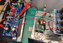
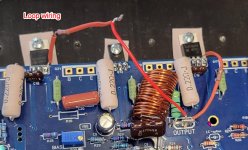
Loop wiring look correct? it measured .794 DCV yesterday.
I removed the board and blew out the board and the heat sink.
Replaced it.
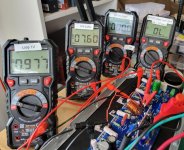
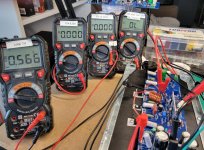
Powered up. R54 = 61.13 DCV R53 = -0.132 DCV
Weird.
Loop wiring look correct? it measured .794 DCV yesterday.
I removed the board and blew out the board and the heat sink.
Replaced it.
Powered up. R54 = 61.13 DCV R53 = -0.132 DCV
Weird.
Attachments
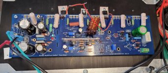
Any likely suspect areas to look at?
I've gone over this board looking for bad solder joints.
How does this board pass the first round of testing: LEDs on, dcv across 10R ~ 0 DCV, and then crap out when I turn it back on for initial bias setting?
Feels like I'm missing something pretty obvious, just not to me.
I've gone over this board looking for bad solder joints.
How does this board pass the first round of testing: LEDs on, dcv across 10R ~ 0 DCV, and then crap out when I turn it back on for initial bias setting?
Feels like I'm missing something pretty obvious, just not to me.
- Home
- Amplifiers
- Solid State
- diyAB Amp The "Honey Badger" build thread