Hi Alex , Hi Aniket . Another member has asked me about a phono stage . We can do a lot on a ready made PCB for less than $1 from RS ( 4 to do the job ) . Problem is he wants it small ( SMD perhaps , perhaps not because good capacitors are large ) . If we get that far any advice ? Even with Gerber files it needs someone to do it . I have seen PCB's for $10 . That seems too good to be true .
Hi Nigel,
I got my PCB's manufactured locally. I sent only the pdf files to manufacturer(he created the gerbers himself). Minimum quantity to order is 15, so i ordered him 16. He charged me 500 Indian rupees (~10$) per PCB, which itself is a good deal, considering the size of the PCB, and they were very good quality.
Hi Alex,
m waiting for the layout file.
Thanks in advance.
Regards,
Aniket
whitch simulation software is usingWith just 24mA bias per device, and 9.3nV DC offset. 980W@2R ultra low THD of 0.169% @ 20kHz, with 5 pairs MJL21193/4. THD could be further reduced using more output pairs.
Just simulated my design, wonder it would perform like this in real.
Regards,
Aniket
Hi guys!
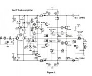
Guys I am on the simple schematic developed this audio amplifier.
Somewhat satisfied with its sound!?
So if you have some ideas about some changes go ahead with the comments.
Regards!
Attachments
Last edited:
I'd just like to say that its voltage slew rate is rather low, at around 5 V/uS. I'm no slew rate freak, but ideally it should be at least 14 V/us to satisfy the criterion of 0.5V/uS per 1 V of peak output. Preferaby 28 V/uS, to satisfy the criterion of 1 V/uS per peak volt output.
In other words, you may experience some slew rate induced distortion (SID) with fast music material. This is distorion caused by an amp's inability to properly track the signal because the input signal is faster than the amp.
Also, I don't see much point in using electronic protection as there is an output fuse.
I think C8 100 pF could be investigated to aid the slewing before a more radical look . Perhaps 47 pF ? C1 also could be reduced until you feel the music lacks sparkle ( aids slewing ) . Each amplifier is different on this . Hypex set the - 3 dB point on their class D amps at around 50 kHz , no one comments on this which surprises me . I wouldn't set it lower on that . Ironically vinyl on piano always seems the best test to me . Percussion seems to need it and vinyl seems better if you have access to a high quality LP source . Even a Technics 1210 is great .
You could remove R13/14 and use a separate PSU at that point . Give it options of 5 V above and 5 V below the output . The below one offers softer clipping , above is maximum power . This can even be a small supply added to the main one in series with a simple zener +transistor regulator . Fast and simple . I measured a regulator like this recently and found it to be 10 dB quieter than a LM317 . I usually add 1 uF film capacitor to the diode to get a good result . The output voltage is zener - 0.7 V . The series resistor should be about enough to run the diode at <50% power rating . Use a small transistor as it will have higher gain and speed . 12 mA at 20 V should be OK for 2N5401 or 5551 . For that the zener might only run at 1 mA . Those transistors should meet any requirement . This is a current amplifier so is the most benign type . Some will go off at a tangent here and start a debate about the best type of regulator . What they forget is the way most amplifiers are is as bad as it is possible to be . Any half descent regulator will be like going from river water to virtually sterile water as an analogy . I am surprised how many do not see this . If a class A amplifier you can not ignore it . Simply stated the problem is camouflaged by class B because the hum is hidden under the music . Truth is it is not hidden as it changes the tonality of the music albeit subtly . Like most people I accept class B as it usually is . It doesn't meant to say it is as good as it can be . The other point is this . Slewing will occasionally be heard . Hum always will be heard . 22 000 uF x 2 is a sensible minimum power supply capacitor . Ideally per channel . When I say hum I don't mean with no music ear to the speaker . I mean oscilloscope on the capacitors playing real music . What you see is being presented to the amplifier . Common mode rejection will do wonders to minimize the effects , wonders should not be taken to be miracles .
Here is a class A amp called Linn Valhalla ( 19 mA standing current into a load of 8.5 mA , turntable PSU ) . No one spotted the hum until 45 rpm was attempted . - 60 dB is a good as I can get it , - 41 db usually . On 33 1/3 rpm it was hidden . The difference in sound is less wow . I have also made the problem better by making 67 Hz the - 3 dB point . Not an option on a hi fi amp . - 80 dB is a good minimum standard ( reference 1 watt ) .
BTW . If running the driver stage 5 V below the output transistors become regulators in their own right just like the zener regulator ( same circuit , same result ) . The ripple is rejected as a currant amplifier will suppress ripple up to the point it intrudes into the peak voltage of the music . With a voltage amplifier this is not true , that is the stage on the separate power supply . Some call this the VAS ( voltage amplifier stage or trans-impedance stage , I to V converter as in a DAC ) . .
So good is a separate power supply that the input current source can be replaced by a single resistor ( to the joined emitters of the input pair ) . Some even argue it sounds better . This might be to do with the frequencies above 10 kHz where the resistor can have better CCRR . A resistor presented with a constant voltage becomes a constant current source . Not least in an input stage where the voltage swing is miniscule . Some talk of the current source being a near infinite resistance and this aids linearity . That is if a voltage amplifier . The input sage is mostly a current amplifier . That being true a resistor probably is better as long as not hum modulated . Even if it is the performance might be still be - 92 dB CMRR ( that is on river water !! ) . I like most people use a current source . I know in my heart I shouldn't .
Last edited:
Nige, you sure threw in a LOT of concepts at this poor man.
The Miller compensation cap, 100 pF. I believe this amp is overcompensated, however, we can't just sit back and auction a value off hand. It can PROBABLY be reduced, but to which value isn't something we can just imagine. It has to be tried in real life, see what happens, if it becomes unstable, go back to last value. Or, alternatively, increase the input stage bias current, this will improve cap charging resulting in improved slew rate.
Power supply stabilization. As you know, this is my default concept, it's something I have been using for 33 years now, and it NEVER fails. But, Gost22 hasn't, so we need to explain the concept to him.
Gost22, the idea is to separate the power supply lines feeding the input stage and the VAS from the lines feeding the current gain stages. The first should be around 5V above the current gain lines so we compensate the inevitablle losses of voltage across the transistors and make sure that no matter what happens in the output stage, the front end will never be influenced by them. Conversly, the output stage can then be run off lower voltages as the preceeding losses have been eliminated. The benefit there is that using lower voltages, we can have more current without breaching the limits of our SOAR curve.
In practice, this works beautifully. The image is solid, the level of detail improves over the current one, etc. All gain, very little pain.
HOW one regulates is another matter. The easiest way is to use a standard 3 pin regulator, say 7824/7924, and install a pair of diodes between their common (ground) pin and the ground, thus "lifting" the ground level by the value of the zener diode. Say, 15V zeners - in conjunction with the regs, this will give you fixed (24+15) 39V lines. The only shortcoming is the noise level, which is not very good with three point regs.
You would do better wusing 317/337 regs in a very similar way, the noise figure would improve.
The best simple way to do it is to use a powerful transistor (e.g. MJE 15030(15031), incoming voltage to collector, zener diode to base determining the output voltage -0.7V normal drop across transistors, outgoing regulated voltage from emmitter. This is preceeded by some serious capacitor filtering, but is also followed by just as serious capacitors, I typically use 2,200 uF. Thus, the transistor feeds the big capacitor right after it, eliminating much more noise than 3 point regs could ever hope for. If the following cap is big enough for the required current, this is also sometimes called a "virtual battery". In their day, Technics for example made much play of that in their top of the line equipment.
But I would warn you - as amps go, this is a very simplistic one and no matter what else you do, you shouldn't expect wonders from it. This is because I believe the initial topology is rather limited; you can't use a 1,100 cc engine to build a Ferrari, you need to start with a really good thing.
It still might sound nice. Off hand, I'd guess that it will provide a warm, cuddly sound, but one lacking dynamism, the fire and brimstone of lively music, and much of its appeal as well.
I think C8 100 pF could be investigated to aid the slewing before a more radical look . Perhaps 47 pF ? C1 also could be reduced until you feel the music lacks sparkle ( aids slewing ) . Each amplifier is different on this . Hypex set the - 3 dB point on their class D amps at around 50 kHz , no one comments on this which surprises me . I wouldn't set it lower on that . Ironically vinyl on piano always seems the best test to me . Percussion seems to need it and vinyl seems better if you have access to a high quality LP source . Even a Technics 1210 is great .
You could remove R13/14 and use a separate PSU at that point . Give it options of 5 V above and 5 V below the output . The below one offers softer clipping , above is maximum power . This can even be a small supply added to the main one in series with a simple zener +transistor regulator . Fast and simple . I measured a regulator like this recently and found it to be 10 dB quieter than a LM317 . I usually add 1 uF film capacitor to the diode to get a good result . The output voltage is zener - 0.7 V . The series resistor should be about enough to run the diode at <50% power rating . Use a small transistor as it will have higher gain and speed . 12 mA at 20 V should be OK for 2N5401 or 5551 . For that the zener might only run at 1 mA . Those transistors should meet any requirement . This is a current amplifier so is the most benign type . Some will go off at a tangent here and start a debate about the best type of regulator . What they forget is the way most amplifiers are is as bad as it is possible to be . Any half descent regulator will be like going from river water to virtually sterile water as an analogy . I am surprised how many do not see this . If a class A amplifier you can not ignore it . Simply stated the problem is camouflaged by class B because the hum is hidden under the music . Truth is it is not hidden as it changes the tonality of the music albeit subtly . Like most people I accept class B as it usually is . It doesn't meant to say it is as good as it can be . The other point is this . Slewing will occasionally be heard . Hum always will be heard . 22 000 uF x 2 is a sensible minimum power supply capacitor . Ideally per channel . When I say hum I don't mean with no music ear to the speaker . I mean oscilloscope on the capacitors playing real music . What you see is being presented to the amplifier . Common mode rejection will do wonders to minimize the effects , wonders should not be taken to be miracles .
Here is a class A amp called Linn Valhalla ( 19 mA standing current into a load of 8.5 mA , turntable PSU ) . No one spotted the hum until 45 rpm was attempted . - 60 dB is a good as I can get it , - 41 db usually . On 33 1/3 rpm it was hidden . The difference in sound is less wow . I have also made the problem better by making 67 Hz the - 3 dB point . Not an option on a hi fi amp . - 80 dB is a good minimum standard ( reference 1 watt ) .
BTW . If running the driver stage 5 V below the output transistors become regulators in their own right just like the zener regulator ( same circuit , same result ) . The ripple is rejected as a currant amplifier will suppress ripple up to the point it intrudes into the peak voltage of the music . With a voltage amplifier this is not true , that is the stage on the separate power supply . Some call this the VAS ( voltage amplifier stage or trans-impedance stage , I to V converter as in a DAC ) . .
So good is a separate power supply that the input current source can be replaced by a single resistor ( to the joined emitters of the input pair ) . Some even argue it sounds better . This might be to do with the frequencies above 10 kHz where the resistor can have better CCRR . A resistor presented with a constant voltage becomes a constant current source . Not least in an input stage where the voltage swing is miniscule . Some talk of the current source being a near infinite resistance and this aids linearity . That is if a voltage amplifier . The input sage is mostly a current amplifier . That being true a resistor probably is better as long as not hum modulated . Even if it is the performance might be still be - 92 dB CMRR ( that is on river water !! ) . I like most people use a current source . I know in my heart I shouldn't .
Hello Nigel!
All this is told in advance ate can view the schematic?

Thank you!
If taking C8 ( Cdom , D Self ) down to 68 pf and maybe 47 pf the loop gain extends and the driving by the input pair becomes easier . As Rod Elliot says at ESP Audio there is a dog chasing it's tail effect by increasing input pair current . Rod concedes that eventually better slewing is arrived at . Making the Cdom as small as possibles helps . Many published designs are conservative to allow for different PCB layout and even fake transistors . They often will say if an oscilloscope is available the design can be optimized . One way to optimize the stability is to increase the gain of the amplifier so that 250 mV = full power . The amplifier often will sound better and distortion will stay low . For example 1 kHz distortion at 1 V sensitivity 0.02 % . Raising it to 250 mV = 0.08% . In realty it is usually better than that . The increase in gain and reduced Cdom might actually reduce 15 kHz distortion . The reason being the loop gain might be increased more than enough to do that . This would start to be a big free lunch . A CD player will drive that nicely with only a volume control ( make input resistance of the amp about 50 K and the volume control, 10 K log ) . 250 mV suits older sources well and simplifies phono stage design .
The stability of Cdom comes from the fact that eventually the amplifier phase inverts at perhaps 200 kHz . Cdom kills the ability of the amplifier to amplify long before that point . The same effect if we hold a microphone near a speaker and get feedback . All we do is walk away from the speaker to kill the feedback ( instability if an amp ) . We can also turn the volume down . Large Cdom turns the volume down and increased gain increases the distance . The big deal is reducing Cdom reduces current demand which increases slewing into the bargain . The PDF is from 1977 . It is not diluted by the passing of time . It was a discovery then . DTN Williamson hints at it in 1947 ( the sound of keys being realistically reproduced , he was 19 years old ! ) . 0.08% distortion mid band is unimportant if not caused by crossover distortion and mostly 2 nd harmonic . 0.08% 15 kHz is a big deal ( better than - 60 dB and no extended harmonics ) . Try to make that between 10 mW and 5 watts , that is almost universally true for any amplifier even if 1000 watts . TDA 3020 can do it .
http://waltjung.org/PDFs/SID_TIM_TAA77_P1.pdf
One of the reason Cdom is placed where it is , is that is transfers loop distortion reduction to local distortion reduction + stability . The problem is more is lost in the process than gained except stability . This is not so much true with class A amps . Here there will be very little difference . The reason being the nasty high harmonics of the crossover distortion are not present if class A . The temptation here is to put the amplifier a little bit into class A . Problem is it usually spends money for no great gain . Having said this your amp might well appreciate it . If crossover distortion is held back until 1 watt it might sound more open . My doubt is the amplifier will get too hot long before it sounds better . If you choose this route the about 1 W threshold will have higher distortion ( spectra doubling ) . Personally I could live with that .
If this instability fascinates anyone study Bootstrapping . It is counter intuitive . The point is bootstrapping is always less than 100 % , in my experience bootstrapping between 50 % and 94 % works . Nyquist instability ( controlled by Cdom ) as it is called in amplifiers is when above 100 % .
One improvement you could do is to make a class A mini amp to drive the tweeters . It only needs to be 2 watts .
Last edited:
Hello Nigel!
All this is told in advance ate can view the schematic?
Thank you!
That and much more, yes, just by looking at the schematic.
Plus what you do not see, because you cannot, the accumulated experience over the decades. I can't even remember the number of German designed amps which looked almost exactly like yours, with only small differences, which genrally sounded warm and cuddly, lovebale for the first half an hour, until you realize that you have marshmellows where there was blood and guts. You discover much of the dynamics of music you know well is now gone, it's all ironed out and soon become boring.
I am particularly acquainted with your model, as a local fellow asked about it a few months ago on a local forum. I took the time and trouble to create a simulation model, which only served to confirm my initial suspicions.
@Nigel
Blimey Nige, you can't just reduce that cap at will. I assume there's a reason why it is so big, I too would have like to have seen something like 33 pF or so.
Personally, I would do BOTH things at once. If you increase the bias current by reducing the value of the emitter resistor on the CCS, your value of C will natirally need to go down. If you double the current, chances are the value of C will halve, in which case you end up with about 4 times bigger voltage slew rate.
Be that so or not, no other way but to make a sample and play with it to see when the amp starts to exhibit signs of instability. It's the only way to include the unknows, such as say the quality of the PCB artwork, which will determine parasitic capacitance as well.
Us old sea dogs Dvv you and I . I said to someone I can sort of hear amplifiers from their circuits . The simple ones are easy enough . Op amps also . One can even upscale op amps to be power amps . The despised LM 741 s probably more sophisticated than a typical simple amp . The Widlar current mirror is from Bob Widlars 741 .
@Nigel
Blimey Nige, you can't just reduce that cap at will. I assume there's a reason why it is so big, I too would have like to have seen something like 33 pF or so.
Personally, I would do BOTH things at once. If you increase the bias current by reducing the value of the emitter resistor on the CCS, your value of C will natirally need to go down. If you double the current, chances are the value of C will halve, in which case you end up with about 4 times bigger voltage slew rate.
Be that so or not, no other way but to make a sample and play with it to see when the amp starts to exhibit signs of instability. It's the only way to include the unknows, such as say the quality of the PCB artwork, which will determine parasitic capacitance as well.
It's like a turbocharger , you can up the boost and it might be unwise . I think you can is you must when it is me . Like wild animals one must take precautions . Tame amplifiers , who needs them ?
Lets be honest Dvv . If anyone wants to learn risk is involved . One can manage risk . Buy some cheap tweeters during test time . Feel the Zobel resistors . If suddenly they are hot the capacitor is too small . If they smoke it is certain . Worse is the C8 capacitor might need to be larger than 100 pf. One can tame amps as TDA 3020 does and make the Zobel at 1 R 100 nF . It will not do any real harm and might help . 4R7 and 100 nF + 16 turn 1 mm wire on 8 mm ID ( 10 mm OD ) is my default output stage .
One needs an inductor in parallel with a resistor at the output only if one's power supply is lacking, and one has inherent design instability issues.
My first job is to make sure I do NOT need them. Anyway, that's a Boucherot circuit, and as most things French, it is perversely unnecessary.
My first job is to make sure I do NOT need them. Anyway, that's a Boucherot circuit, and as most things French, it is perversely unnecessary.
Hello dvv!That and much more, yes, just by looking at the schematic.
Plus what you do not see, because you cannot, the accumulated experience over the decades. I can't even remember the number of German designed amps which looked almost exactly like yours, with only small differences, which genrally sounded warm and cuddly, lovebale for the first half an hour, until you realize that you have marshmellows where there was blood and guts. You discover much of the dynamics of music you know well is now gone, it's all ironed out and soon become boring.
I am particularly acquainted with your model, as a local fellow asked about it a few months ago on a local forum. I took the time and trouble to create a simulation model, which only served to confirm my initial suspicions.
*Mr. dvv if you are able to give everything you have said about my schematic audio amplifiers send the Serbian language to my e-mail address (Send private message to Gost22)!
thank you!
Ziveli!!

Attachments
Last edited:
- Status
- This old topic is closed. If you want to reopen this topic, contact a moderator using the "Report Post" button.
- Home
- Amplifiers
- Solid State
- Simple 100W power amp