I'm trying to build a class-A buffer for a transformer-based headphone amplifier. The idea is to have a very transparent buffer so the distortion of the transformer can be heard. The distortion of transformers is very nice from a theoretical point of view (it decays with frequency, which may allow to have a sweet midrange and clean voices), and has low intermodulation. It can also be increased by adding a small bias current.
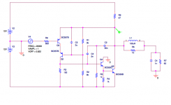
After some playing in spice I've come out with the attached design. Distortion is excellent: 0.0001 % THD (almost all second harmonic) at 1 Vpk and 20KHz, which should drive my pair of AKG 701 to the unhealthy SPL of 102 dB's. It also has power to get to more than 110 dB's so there is headroom for peaks, which will have a slightly increased distortion. It should be noted that this is a huge improvement when compared to class-B operational amplifiers of the breed of the LM4562, which performs better at 1Vrms but distortion skyrockets at lower volumes which will constitute most of my listening, and it also contains less benign higher harmonics.
I'm having a couple of problems with this design. The first one is that I need a transistor for the output stage. The BC550B that I'm using in the simulations would blow up immediately if used with this current, but most power transistors are too powerful and too sluggish. I'm looking for something in the vein of the 2SC3505 but with slightly higher current capability (even if it comes at the price of lower breakdown voltage, certainly I do not intend to go near 300V). Any idea of how a power JFET would behave there? They seem very fast and don't have problems at 250 mA, but they are hard to find and poorly modeled in spice. Cascoding is another option but it comes at the price of decreased stability when compared to a single high-frequency transistor.
The second problem is not exactly a problem but an issue I'd like to improve on, and it is stability. The square wave response, while stable up to 500 pF loads, shows some nasty ringing that I'd rather not see. Obviously I can increase compensation until it goes away, but this would come at the expense of higher distortion. What would be really great is to make the amplifier faster, so the poles that are causing the ringing went upper in frequency were the gain is lower. I would appreciate very much hearing suggestions in this aspect.
Disclaimer: This is untested, design-stage schematic. While it is intended to work, it may need some modifications (the most notorious is the change of Q5 and the addition of a DC servo) and may present stability issues.
Attachments
I'm trying to build a class-A buffer for a transformer-based headphone amplifier. The idea is to have a very transparent buffer so the distortion of the transformer can be heard. The distortion of transformers is very nice from a theoretical point of view (it decays with frequency, which may allow to have a sweet midrange and clean voices), and has low intermodulation. It can also be increased by adding a small bias current.
You been reading Bill Whitlock?

se
You been reading Bill Whitlock?
se
Yes. There are things about tube sound which I like, but I find the sound not clean enough. I've been wondering if using a transformer I could get the best of both worlds.
Do you have experience with transformers in audio? This dude is suspicious because of the interest in his company.
I think you'll be quite happy with the transformers. I like tubes too but found I like transformers better when it comes to voltage gain.
If you're not already familiar with them, check out CineMag (Audio Transformers By Cinemag Inc.). Specifically their CMMI-5C.
se
If you're not already familiar with them, check out CineMag (Audio Transformers By Cinemag Inc.). Specifically their CMMI-5C.
se
My idea is to use a 150:600 step up transformer, hence the 600 Ohm resistor in the source. I see both CineMag and Jensen do manufacture them. The CineMag has some nasty peaking at 150 KHz, but in the Jensen the distortion is quoted at -20 dBu, so I have no idea how they will perform at normal listening levels around 0 dBu.
CineMag:
http://cinemag.biz/mic_input/CMMI-2C.pdf
Jensen:
http://www.jensen-transformers.com/datashts/16a.pdf
Lundahl also makes transformers with higher turns ratio (and probably worse bandwith and distortion). If they costed the same as resistors I would buy one of each.
CineMag:
http://cinemag.biz/mic_input/CMMI-2C.pdf
Jensen:
http://www.jensen-transformers.com/datashts/16a.pdf
Lundahl also makes transformers with higher turns ratio (and probably worse bandwith and distortion). If they costed the same as resistors I would buy one of each.
My idea is to use a 150:600 step up transformer, hence the 600 Ohm resistor in the source.
Oh, ok. Don't know that I'd want to use a line output transformer as an input transformer. Hence my recommendation of the CMMI-5C.
I see both CineMag and Jensen do manufacture them.
That's because in a way, Jensen transformers are CineMag transformers.
Ed Reichenbach designed all the transformers for Deane Jensen back when Deane started Jensen Transformers. In fact, they were originally billed as "Jensen Transformers by Reichenbach Engineering." Deane split from Ed and basically took the engineering with him.
CineMag was started by the late Tom Reichenbach, Ed's son, and he has all the Reichenback engineering that was done for Deane.
The CineMag has some nasty peaking at 150 KHz...
What source material were you planning to feed it that has content at 150kHz?
Also note that the Jensen's using an RC snubber in parallel with 6.19k load resistor. So if that 150k resonant peak freaks you out, you can just use the same snubber on the CineMag.
...but in the Jensen the distortion is quoted at -20 dBu, so I have no idea how they will perform at normal listening levels around 0 dBu.
Well they both show THD versus frequency for fixed levels, so you can pretty much interpolate from there.
se
Oh, ok. Don't know that I'd want to use a line output transformer as an input transformer. Hence my recommendation of the CMMI-5C.
That's because in a way, Jensen transformers are CineMag transformers.
Ed Reichenbach designed all the transformers for Deane Jensen back when Deane started Jensen Transformers. In fact, they were originally billed as "Jensen Transformers by Reichenbach Engineering." Deane split from Ed and basically took the engineering with him.
CineMag was started by the late Tom Reichenbach, Ed's son, and he has all the Reichenback engineering that was done for Deane.
What source material were you planning to feed it that has content at 150kHz?
Also note that the Jensen's using an RC snubber in parallel with 6.19k load resistor. So if that 150k resonant peak freaks you out, you can just use the same snubber on the CineMag.
Well they both show THD versus frequency for fixed levels, so you can pretty much interpolate from there.
se
In fact they are sold as mic-in transformers and not line out, pretty much like the one you linked me to, only they have less gain (which is OK since I never listen to my sources at full power. I guess 2x gain is already fine)
My concern for the 150KHz peaking is probably coming from solid-state design experience, which would indicate poor stability. But I will definitely add the snubber just to be sure that there is no digital high-frequency noise, where the amplifier is less stellar, getting augmented by the transformer and then demodulated by the amplifier.
Since you seem to be really into audio transformers, do you have any reason to prefer CineMag to Jensen?
By the way, I appreciate your comments about transformers and they are going to be helpful for my amplifier, but I would like to restate my questions about the solid-state output stage, since it is where I'm really stuck and I think I'm quite close to do significantly better than the most headphone buffers out there.
I reattach the schematic in PNG format for those who don't like to open PDF's.
Attachments
In fact they are sold as mic-in transformers and not line out, pretty much like the one you linked me to, only they have less gain (which is OK since I never listen to my sources at full power. I guess 2x gain is already fine)
Yeah, I know. But when you said "150:600," first thing that comes to my mind is a line output transformer wired 1:2.
My concern for the 150KHz peaking is probably coming from solid-state design experience, which would indicate poor stability.
Another nice thing about transformers. They don't oscillate.
Since you seem to be really into audio transformers, do you have any reason to prefer CineMag to Jensen?
Because I find them to be just as good, cost less, and when I call CineMag, I get the president of the company on the phone. Not some hired tech.
By the way, I appreciate your comments about transformers and they are going to be helpful for my amplifier, but I would like to restate my questions about the solid-state output stage, since it is where I'm really stuck and I think I'm quite close to do significantly better than the most headphone buffers out there.
I'm working on my own for a commercial amplifier so I'll leave that for others to respond to.
se
Look at "the wire" thread here... it uses a bunch of ultra-super low distortion buffer chips in parallel as a power amp output stage, iirc. You could use just one.
Also, I would expect ringing into a capacitive load with an inductor at the output.
You don't need that if the circuit will not destroy itself into an ultrasonic virtual short circuit (very low Z) - which is merely a capacitive load...
Consider paralleled devices if you need speed and can not find speed in a single device?
_-_-bear
Hi
If you're not apposed to I.C's then the buff634 in high bandwidth mode could be a simple solution
Thank you for your suggestion. I did a considerable amount of research before deciding to build my circuit, and I found there was not an actual reference buffer that had a truly great following. In fact most of what's out there falls in three categories:
- Simple followers (For some reason people love to build them using FETs, even when they usually have large distortion and some not-so-benign high-order harmonics)
- Random stuff in the feedback loop of an op amp
- Diamond buffers (either integrated like the one you mentioned or discrete)
The first ones just don't do well compared to more elaborate topologies. The stuff in the feedback loop of an opamp does well but I think its quite inelegant, besides the fact that the opamp is a class-b circuit and in a headphone amplifier it will literally not leave the crossover region. Crossover distortion is not as nice as the second harmonic from single-ended class-A. Stability may also be a pain if it operates as a follower. The BUF634 that you pointed out has the problems of class-B, and I think distortion-wise it does well but its not great.
So basically I've decided to try my shot at a reference buffer for headphone applications. Certainly if my present design behaves as well in reality as it does in simulations I may be close to have just done it.
Look at "the wire" thread here... it uses a bunch of ultra-super low distortion buffer chips in parallel as a power amp output stage, iirc. You could use just one.
Also, I would expect ringing into a capacitive load with an inductor at the output.
You don't need that if the circuit will not destroy itself into an ultrasonic virtual short circuit (very low Z) - which is merely a capacitive load...
Consider paralleled devices if you need speed and can not find speed in a single device?
_-_-bear
If i'm well informed, The Wire is based on the LME49830. This would be 100x overkill for my headphone amp!
Regarding the circuit destroying itself when connected to a capacitive load. I measured my headphone cable capacitance to be around 1 nF. This was too much for my previous design, but the present iteration seems to hold it well and therefore I will remove the RL network from the design.
When I discussed ringing, I meant ringing at the output of the amplifier, before the load. This ringing is due to the phase margin not being high enough, and it is bad stuff because in my experience phase margins are always lower in reality than they are in spice.
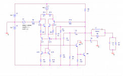
Now I have replaced the input transistor by a Sziklai pair taken from Douglas Self book and the performace seems much better. I get a THD 0.0002% of (almost) purely second harmonic at 20 KHz 1Vpk an and a nice, critically damped square wave response on 1 nF without filtering. Please see the attached schematic (Disclaimer, it is untested and may not work, or even blow your headphones). If I can beat the 0.0001% THD mark I'll design a PCB. It would be awesome to see people changing the parts I've chosen because they sound bad
. (Please note that I have not invented this circuit. It's close to an output-stage-less blameless amp with two pole compensation.EDIT: But it has my contribution! While Douglas Self says cascoding the input stage does not make a difference, I've found that in this circuit does indeed provide an improvement by a factor of 10 in the distortion. I guess it is because of the non-inverting unity gain operation.
Attachments
Last edited:
your assumptions about monlithic op amps are wrong/outdated
op amps driving output buffers usually work Class A in all stages - the output of most "audio recommended" op amps are internally biased ~100 uA or more (based on indirect evidence from open loop output Z plots), driving 100+ kOhms, single digit pF at the buffer input they never leave Class A for audio signals
if you want deeper Class A output bias people have long loaded op amp output with few mA ccs to one rail to force the output into SE Class A - depending on op amp, fab tech the rail polarity, current magnitude may vary for "best" distortion - disappointingly for most the only measured improvements with this technique I've seen published are < 10 dB distortion improvement
while "discrete is superior" is well established meme in audio - I would claim for most consumer line level audio applications it has fallen to the technological advance of monolithic process development and design expertise at major linear op amp manufacturers competing for precision instrumentation, medical imaging, telcom markets over the past 20 yrs - it is no longer 1970s
you may say the “the wire” is overkill but it or related op amp + monlolithic buffer circuits take lots less design effort for results you are unlikely to approach within orders of magnitude with available discretes, less than decades of design experience
look at TI’s OPA164x series as a modern example of current performance for “audio” – if you have high source Z then consider OPA827 as a cheaper update to the OPA627 if low order ppm distortion from the input jfet parasitic C modulation worries you
From the audible results (not from the measurement results) this is my favourite design:
the Power Folllower
You must choice the suited idle current in order to the individual load impedance from your headphone.
the Power Folllower
You must choice the suited idle current in order to the individual load impedance from your headphone.
while "discrete is superior" is well established meme in audio - I would claim for most consumer line level audio applications it has fallen to the technological advance of monolithic process development and design expertise at major linear op amp manufacturers competing for precision instrumentation, medical imaging, telcom markets over the past 20 yrs - it is no longer 1970s
I agree with you in the fact that modern op amps behave better than what is achievable with discrete parts, but they still require the buffer stage to drive a pair of headphones. What I'm trying to do here is to improve in the CFP buffer stage to get it to perform comparably to the globally closed-loop system with the opamp. It may be just a matter of elegance to improve a stage that is already on the design so it makes another stage unnecessary, and the overall performance may be marginally minor (You will probably agree with me that a class-A buffer with 0.0002% THD will not sound much worse than an opamp with 0.00004% THD), but I'm definitely interested in finishing this design.
you may say the “the wire” is overkill but it or related op amp + monlolithic buffer circuits take lots less design effort for results you are unlikely to approach within orders of magnitude with available discretes, less than decades of design experience
I must disagree with you on the orders of magnitude thing. If there is the blameless amplifier that can repeatedly drive 8 Ohms loads to 50W with < 0.0008% THD, It must be possible to drive headphones to a few milliwatts with 0.0002% THD. This is not within orders of magnitude of audio opamps. Please note that I respect very much the designers of such IC's. They do 5 or 6 times better than my design goal with microamperes of bias current, while I'm running all the stages so hot that they only use a small portion of their transconductance curve. But I think an output stage can be made clean enough so as to simply not get any audible benefit from the opamp.
From the audible results (not from the measurement results) this is my favourite design:
the Power Folllower
You must choice the suited idle current in order to the individual load impedance from your headphone.
This is a high-distortion design. While I agree that some distortion may add a nice character to the sound, what I'm trying to do in this project is to add such character by using a transformer, so I can choose the amount of distortion that I want by changing the transformer dc bias current, so it's important that the output stage is of low distortion.
Last edited:
I'm just hunting around the Internet for a design that I found a few months ago, it was based in the CMOY amp but used two BURR-BROWN op-amps in parallel.
In the meantime this looks interesting KS Projects - High End Headphone Amplifier
In the meantime this looks interesting KS Projects - High End Headphone Amplifier
you are looking at the wrong 'the wire' design. the wire is a series of well characterised (with an audio precision system) amps, the first of which were buffered BAL-SE instrumentation amps for headphones and followed through SE-SE, BAL-BAL and a reworked BAL-SE see wiki for schematics
then there is the hybrid lme49830 lateral mosfet power amp and the one the bear is talking about that features paralleled buffers is called the LPUHP (low power ultra high performance) amp which is a ~16wpc speaker amp that can also be used for VERY current hungry headphones and features performance that matches the headphone amps but drives speakers, was designed for multiamped digital/active crossovers. the numbers on it are about half way down the page, but even with the AP system, he was unable to get any meaningful results, as the input preamp and ADC of the AP is outclassed by the amp. at 10W/1khz we are below your 0.0002% THD
then there is the hybrid lme49830 lateral mosfet power amp and the one the bear is talking about that features paralleled buffers is called the LPUHP (low power ultra high performance) amp which is a ~16wpc speaker amp that can also be used for VERY current hungry headphones and features performance that matches the headphone amps but drives speakers, was designed for multiamped digital/active crossovers. the numbers on it are about half way down the page, but even with the AP system, he was unable to get any meaningful results, as the input preamp and ADC of the AP is outclassed by the amp. at 10W/1khz we are below your 0.0002% THD
Last edited:
at 10W/1khz we are below your 0.0002% THD
I'm sure it sounds dramatically better, as long as listening to 105 dB music sensitizes you to -10 dB acoustic signals.
Seriously, I'm just trying to build a linear buffer stage. It is an inoffensive, 5 bucks project (I have the heatsinks and transformers) and it's likely to sound quite good from the simulations, besides of being extremely instructive. I started this thread becasue I hoped to get some feedback from the circuit, but everybody seems convinced that I should be building something else.
Besides this, I once built a class-B mosfet output stage to run inside an LM4562 feedback loop, and I must confess I did not hear much of a difference from closing the loop, and it simulated 0.1% crossover distortion!
Last edited:
Here is the oddball that falls in none of these categories:Thank you for your suggestion. I did a considerable amount of research before deciding to build my circuit, and I found there was not an actual reference buffer that had a truly great following. In fact most of what's out there falls in three categories:
.
- Simple followers (For some reason people love to build them using FETs, even when they usually have large distortion and some not-so-benign high-order harmonics)
- Random stuff in the feedback loop of an op amp
- Diamond buffers (either integrated like the one you mentioned or discrete)
http://www.diyaudio.com/forums/head...glinator-mos-based-tringlotron-amplifier.html
The TringloMOS output stage is unity-gain, operates in class A, has a very low distortion, and is ideally suited to transformers.
And it won't set you off more than 5 bucks
Here is the oddball that falls in none of these categories:
http://www.diyaudio.com/forums/head...glinator-mos-based-tringlotron-amplifier.html
The TringloMOS output stage is unity-gain, operates in class A, has a very low distortion, and is ideally suited to transformers.
And it won't set you off more than 5 bucks
It's really nice to see something new. I'll certainly find some time to build one of these
.You know, the real world implementation of your 0.0001% design is very unlikely to do that right out of the "box" - I suspect that you would have to trim just about everything and match devices to get it there - not to mention the power supply too... I suspect you know that already.
_-_-bear
_-_-bear
- Status
- This old topic is closed. If you want to reopen this topic, contact a moderator using the "Report Post" button.
- Home
- Amplifiers
- Solid State
- Suggestions for a very low distortion class A headphone buffer