You know, the real world implementation of your 0.0001% design is very unlikely to do that right out of the "box" - I suspect that you would have to trim just about everything and match devices to get it there - not to mention the power supply too... I suspect you know that already.
_-_-bear
Agreed, although I'm trying to make a robust design, by using emitter degeneration and lots of negative feedback, so it does not rely (much) on parts. I'm playing with the values and trying to identify which values are the most critical and which ones can take any value within a reasonable range.
Funny little mind twister, eh?Elvee - that is one heck of a circus you posted! I mean circuit.
Too bad it isn't DC coupled.
I worry about caps in the signal path.
Will have to read that thread again and stare at the schematic until it sinks in. Heh.
_-_-bear
Agreed on the distortion with discrete devices, you would need to hand-pick them with great care, and couple them thermally, but fortunately there is an alternative, dual monolithic transistors like this one:
http://www.datasheetcatalog.org/datasheet/vishay/70758.pdf
This solves all the problems at once.
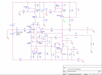
I've finally got to my design goal, in spice distortion is 0.00004% with 0.00003% second harmonic and 0.00001% 4rd harmonic at worst case (1V, 20 KHz). At a possible listening level of 0.5V and 2KHz SPICE shows no distortion. Stability seems fine, slew rate is good, and a 5R in series with the supplies doesn't make any difference. I have also played with parts values, and most of them tolerate changes of 50% or more without significant changes in distortion. The symmetric parts seem to tolerate well mismatches of 1%, and I've just bought 0.1% resistors.
Please note that this is a simulation result and I have no idea how the actual circuit will behave. Hopefully I'll be able to post distortion measurements soon .
.
Please note that I appreciate very much all of the suggestions that people have made, but designing one's own amplifier is a satisfaction I was not going to let go, and I've spent an entire rail of LM4562's building headphone and small loudspeaker amplifiers.
I agree that Elvee's designs are mind-twisting!
Disclaimer: This circuit is the result of a simulation exercise done in good faith and with the intention of building it, however it has not been tested yet and it may behave in unexpected ways. I take no responsibility of anything that happens if you build it, including broken headphones or sources.
Please note that this is a simulation result and I have no idea how the actual circuit will behave. Hopefully I'll be able to post distortion measurements soon
.Please note that I appreciate very much all of the suggestions that people have made, but designing one's own amplifier is a satisfaction I was not going to let go, and I've spent an entire rail of LM4562's building headphone and small loudspeaker amplifiers.
I agree that Elvee's designs are mind-twisting!
Disclaimer: This circuit is the result of a simulation exercise done in good faith and with the intention of building it, however it has not been tested yet and it may behave in unexpected ways. I take no responsibility of anything that happens if you build it, including broken headphones or sources.
Attachments
Last edited:
That s a typical so called blameless topology popularized by D. Self
but was in fact used in most 70s opamps , including the 741.
Compensation has seemingly too low cap values , so low that
it s somewhat as much a two pole as a shunt compensation,
the latter being also implemented.
but was in fact used in most 70s opamps , including the 741.
Compensation has seemingly too low cap values , so low that
it s somewhat as much a two pole as a shunt compensation,
the latter being also implemented.
The circuit in post 24 doesnt use a transformer at all, except for the supply rails.
Are you really wanting to spend 2000 $ for a heaphone amp only because of its use of a transformer which by the way is technically inferior in all ways I can think of.
You could just spend maybe around 50 euros and get a excellent good sounding headphone amp. I think your wife is going to wring your neck.
- Status
- This old topic is closed. If you want to reopen this topic, contact a moderator using the "Report Post" button.
- Home
- Amplifiers
- Solid State
- Suggestions for a very low distortion class A headphone buffer