You can actually put your name here:
https://docs.google.com/spreadsheet/ccc?key=0AjoWwC_y8PtfdG9OZEN0T25aeTlZcHpkcHhxVUQ2clE#gid=0
https://docs.google.com/spreadsheet/ccc?key=0AjoWwC_y8PtfdG9OZEN0T25aeTlZcHpkcHhxVUQ2clE#gid=0
@chchyong89:
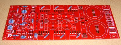
I have started doing the build today (see attached image) and will go on matching the small transistors (BC550C, BC560C, ...,
the HFe matching will be done using my DMM) and solder them tomorrow.
I have begun with the resistors, and as you can see: I am using standard metal resistors.
I will use "standard" components throughout this build, but I will use carefully matched input transistors (LSK170)
and closely (< 5% HFe, VBe) matched output transistors.
I will then try and prepare the heatsink.
This will be the biggest challenge for me: I am not a craftsman at all!
Take a look at this thread once a week or so.
This is no longer a "group-buy thread" currently.
I would like and call it: "My FC-100 prototype building blog".
If I succeed with this AMP (designed by Mihai, the PCB being layouted by METAL and me), this thread will contain
all the information necessary to do it yourself.
I will keep you informed about my progress.
Best regards - Rudi_Ratlos
Attachments
@chchyong89:
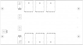
The size of the heatsink needs to be bigger than 104 x 191 mm (see the attached image of the drill-master).
A heatsink with a height of 100 mm may be a little bit short.
I will use an old 100 mm heatsink for the prototype as well.
I will not yet use the heatsink shown in post #140; I have to obtain some experience drilling and mounting the transistors beneath the PCB first.
@Dave:
Mihai's FC-100 AMP needs a transformer with 2 x 25 VAC secondaries for the backend and a small transformer with 2 x 34 VAC secondaries for the frontend.
Mihai designed a shunt-regulator at +/-39 VDC to power the frontend.
I have layouted this shunt-regulator as well (shown in post #130), but I am still waiting for the prototype to be etched.
If you would like building a prototype as well: my offer #2 is still to have.
Best regards - Rudi
Attachments
@chchyong89:
The size of the heatsink needs to be bigger than 104 x 191 mm (see the attached image of the drill-master).
A heatsink with a height of 100 mm may be a little bit short.
I will use an old 100 mm heatsink for the prototype as well.
I will not yet use the heatsink shown in post #140; I have to obtain some experience drilling and mounting the transistors beneath the PCB first.
Best regards - Rudi
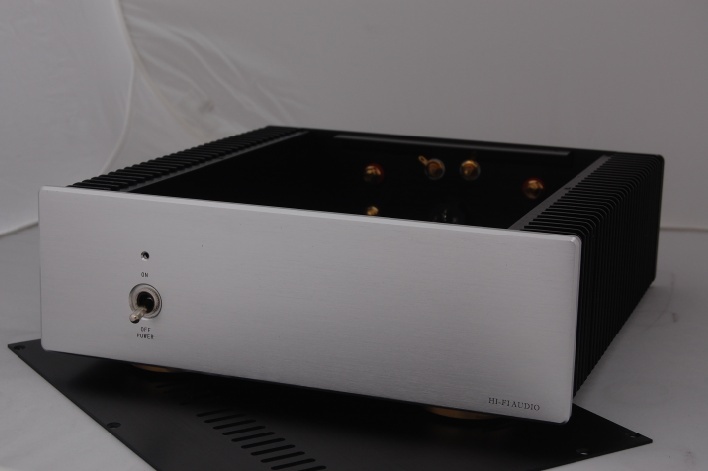
I found this casing from china website and it cost roughly 60usd. I love it very much but the size is very compact @ 220*85*300mm(inner).
 I wish to build this amplifier and fit into a small casing that can do everything for me without wasting space.
 I think I will try to draw a PCB to fit into the case by using 1/8 resistors or 0805 SMD.
I have checked the Nover 10,000uF/63v and 1,000uF/63V, the diameter is relatively small at just 30mm and 16mm diameters respectively.
Hope Mihai would give me a permit to do that.
Last edited:
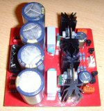
I received the prototype of Mihai's shunt PCB yesterday (the layout follows exactly the schematics in post #45 of the RMI FC-100 thread)
and built the positive regulator.
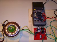
The transformer I use is 2 x 35VAC at 120 Watt.
I used a 2K2 resistor as load resulting in a current of about 19mA.
The good news: the shunt did not explode
The bad news: the output shows 40.5V (instead of 39V), and I wonder if it is as stable as it shall be.
The value that my DMM is showing changes rapidly between 40.3 VDC to 40.7 VDC).
I do not know the power requirement of the FC-100 frontend; I did not find it in the thread.
Maybe my assumption of about 20mA per rail is absolutely wrong.
Is there anybody who knows the exact current rating of the FC-100 - frontend?
Best regards - Rudi_Ratlos
and built the positive regulator.
The transformer I use is 2 x 35VAC at 120 Watt.
I used a 2K2 resistor as load resulting in a current of about 19mA.
The good news: the shunt did not explode
The bad news: the output shows 40.5V (instead of 39V), and I wonder if it is as stable as it shall be.
The value that my DMM is showing changes rapidly between 40.3 VDC to 40.7 VDC).
I do not know the power requirement of the FC-100 frontend; I did not find it in the thread.
Maybe my assumption of about 20mA per rail is absolutely wrong.
Is there anybody who knows the exact current rating of the FC-100 - frontend?
Best regards - Rudi_Ratlos
Attachments
Joe,
I played around with the load resistor's value for some time, and when I inserted a 1K I saw a very stable 39V for the first time.
1K @ 39V: this means that the frontend needs about 40mA current!
I know the AMPs of Carlos that need about 12-15mA.
I know Michael Bittner'S SYMASYM very well. This one needs 8mA!
But since Mihai has certainly matched the shunt to the frontend of his AMP, this value must be true.
Find attached a picture of the prototype-shunt PCB.
I am thinking of including it on the left side of the AMP's PCB.
The distance from the AC-section of the shunt to the input and small signals is about 7 cm and there is a big power-plane between.
Therefore I do not think that the AC section will interfere with the small signals.
What is your opinion, Joe? May I?
Best regards - Rudi_Ratlos
Attachments
Last edited:
rudi, I would suggest taking that beautiful scope of yours and look at the ripple content,at your load current of 40 ma. If you see any spikes in the waveform you can bypass c13 and c14 with a .1mfd cap to ground,,to prevent any noise pick-up from your zeners, it also may not be needed. And thank you for your kind words. Evette
Joe,
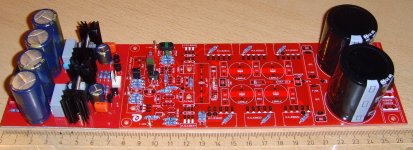
this is what I am bearing in my mind to offer to you:

http://www.abload.de/img/shunt0126nuo3.jpg
A big "whale-PCB" (as Carlos would have said), containing the frontend-PSU on the left and the backend-PSU on the right side.
I will check the frontend-PSU with my oscilloscope tomorrow and will then go on with the AMP PCB.
Best regards - Rudi
Attachments
Mr. Rudi Sir,,YOUR THE MAN,,I,m so proud of the work that you and Mr.Metal Produce that tears come to my eye,s. You,ve come a long way This is your best work so far,.,please don,t stop. Words can,t express what I see in the quality of work you and Mr, Metal produce. so DON,T STOP. great,, Evette
I feel proud that you love our work, thank you very much for your nice words indeed, I hear them coming out of your heart :- ) This PCB took considerable amount of time and hence, effort to make it as is now.
Now we need to see how to complete this project, whether to put the shunt on the amplifier PCB or not, all inputs are welcome.
Now we need to see how to complete this project, whether to put the shunt on the amplifier PCB or not, all inputs are welcome.
- Status
- This old topic is closed. If you want to reopen this topic, contact a moderator using the "Report Post" button.
- Home
- Amplifiers
- Solid State
- Roender's FC-100 prototype and builder's thread