Hello Rudi,
Thank you for keeping informed us.
from Rudi:
"I made an extra solder-shift especially for you."
I'm sure all of us are very thankful for your great effort.
from Rudi:
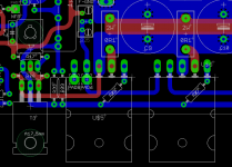
"The solder-pads of the emitter-resistors are very, very small and the isolation ring around them is very small as well.
Be very careful, when you solder the emitter resistors and measure with a DMM the resistances to the rail-voltages and GND.
An "error" like this happens, when you do the layout on a 25-inch flatscreen and zooming the layout by means of the layout software."
I use eagle cad to creat pcb and when i feel finished the pcb i print the 1:1 size on peaper and try to fit the parts on it and check how it looks like in reality. But i must tell you that i'm not so good at designing pcb.
BTW the boards look nice on the heatsink.
I'll start to match the parts on the weekend.
Best Regards,
zsaudio
Thank you for keeping informed us.
from Rudi:
"I made an extra solder-shift especially for you."
I'm sure all of us are very thankful for your great effort.
from Rudi:
"The solder-pads of the emitter-resistors are very, very small and the isolation ring around them is very small as well.
Be very careful, when you solder the emitter resistors and measure with a DMM the resistances to the rail-voltages and GND.
An "error" like this happens, when you do the layout on a 25-inch flatscreen and zooming the layout by means of the layout software."
I use eagle cad to creat pcb and when i feel finished the pcb i print the 1:1 size on peaper and try to fit the parts on it and check how it looks like in reality. But i must tell you that i'm not so good at designing pcb.
BTW the boards look nice on the heatsink.
I'll start to match the parts on the weekend.
Best Regards,
zsaudio
Gentlemen,
I am having a strange problem currently, which I cannot explain.
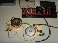
This is my build:

http://www.abload.de/img/poweron029h8a8v.jpg
a light-bulk tester (40W) connecting to the backend- (2 x 25VAC) and the frontend- (2 x 34 VAC) transformer.
As I wrote in a former post, the frontend of the FC-100 (being driven from the shunt-PCB) looked good
(all the green and red LEDs are shining luckily), and I was seeing my applied sine-wave on the MJE driver's emitter/collector.
I connected the backend-PSU today (of course I checked it beforehand), switched power on and: the frontend-LEDs are not shining anymore!
and the voltage-drop over a emitter-resistor is about 60mV.
When I connect the backend-PSU, the frontend-shunt-regulator will be turned off ?!
I have to check the reason for this.
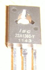
My Canadian friend suspects the used 2SA1360 / 2SC3424 (T3 and T4 are the interrfaces between frontend- and backend voltage),
and I will examine them once more very closely.
When I matched them, they looked 'honorable', having a HFe about 130 (2SA1360) and 165 (2SC3423).
I am sorry not being able to give you the "GO" for my PCB yet.
Best regards - Rudi_Ratlos
I am having a strange problem currently, which I cannot explain.
This is my build:

http://www.abload.de/img/poweron029h8a8v.jpg
a light-bulk tester (40W) connecting to the backend- (2 x 25VAC) and the frontend- (2 x 34 VAC) transformer.
As I wrote in a former post, the frontend of the FC-100 (being driven from the shunt-PCB) looked good
(all the green and red LEDs are shining luckily), and I was seeing my applied sine-wave on the MJE driver's emitter/collector.
I connected the backend-PSU today (of course I checked it beforehand), switched power on and: the frontend-LEDs are not shining anymore!
and the voltage-drop over a emitter-resistor is about 60mV.
When I connect the backend-PSU, the frontend-shunt-regulator will be turned off ?!
I have to check the reason for this.
My Canadian friend suspects the used 2SA1360 / 2SC3424 (T3 and T4 are the interrfaces between frontend- and backend voltage),
and I will examine them once more very closely.
When I matched them, they looked 'honorable', having a HFe about 130 (2SA1360) and 165 (2SC3423).
I am sorry not being able to give you the "GO" for my PCB yet.
Best regards - Rudi_Ratlos
Attachments
Last edited:

Yes, I have, Neb.
The shown wire is the connection between frontend-GND and backend-GND.
I am currently powering-up the AMP from the backend-PSU only.
The light-bulk tester remains dark. Good.
I will now measure the voltages on the 2SA1360 and 2SC3423 and will report them.
Best regards - Rudi
The shown wire is the connection between frontend-GND and backend-GND.
I am currently powering-up the AMP from the backend-PSU only.
The light-bulk tester remains dark. Good.
I will now measure the voltages on the 2SA1360 and 2SC3423 and will report them.
Best regards - Rudi
Last edited:
Sorry for misread your post but as i understood from your previuos post the front and backend psu were connected inthe same time. In this case the ground wire on the picture posted by me (originally by Roender) must be inserted.
from Rudi:I connected the backend-PSU today (of course I checked it beforehand), switched power on and: the frontend-LEDs are not shining anymore!
and the voltage-drop over a emitter-resistor is about 60mV.
When I connect the backend-PSU, the frontend-shunt-regulator will be turned off ?!
waiting for your findings
Regards,
zsaudio
Do you have frontend and backend PSU connected after same bulb tester? If yes, read on:
Light bulb (60W approx) tester will work only with backend completely underbiased; if you biased backend at 18-20mV across Re as it should be, bulb will drop the voltage so much that it will kill the frontend and shut everything down.
Light bulb (60W approx) tester will work only with backend completely underbiased; if you biased backend at 18-20mV across Re as it should be, bulb will drop the voltage so much that it will kill the frontend and shut everything down.
@ZDR, Evette,
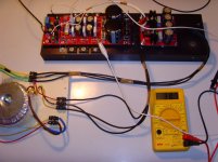
I disconnected the frontend-shunt regulator from the light-bulb tester (I left the backend PSU attached to it) and switched power on again this morning.
Things look much better now.
Thank you for this advice, ZDR.
The frontend-LEDs shine happy again and the light-bulb does not shine that bright anymore.
But: there is still something wrong.
The minimum voltage drop over a emitter-resistor (the value of the trim-resistor being 0 Ohm at that time) is 48mV (see attached image).
It should be 0mV!
If I increase the trim-resistor's value, the voltage drop increases as well.
This is at least a good sign.
I will now measure the voltage drop over each integrated diode.
Any advice is welcome.
Best regards - Rudi_Ratlos
P.S. The image is shows a faulty measurement! The text above is correct.
Attachments
Last edited:

Hello Rudi,
I had the same issue in ltspice simulation when i rised the VAS current. If you have ltp current and vas current like it should be, measure the base voltages of q19 and q20. These are about 1.2v, -1.3v in simulation, the real life measurements may differ. Maybe someone who built it can help you what are the real values.

Regards,
zsaudio
I had the same issue in ltspice simulation when i rised the VAS current. If you have ltp current and vas current like it should be, measure the base voltages of q19 and q20. These are about 1.2v, -1.3v in simulation, the real life measurements may differ. Maybe someone who built it can help you what are the real values.
Regards,
zsaudio
@ZSAUDIO,
the voltages on Q19 (2SC3423) are:
Emitter: 0.66V
Collector: 15.42V
Base: 1.26V
The voltages on Q20 (2SA1360) are:
Emitter: -0.66V
Collector: -15V
Base: -1.23V
That looks good.
Best regards - Rudi_Ratlos
P.S. I do not have the LTSpice files for the FC-100. If you have: can you please them to me?
the voltages on Q19 (2SC3423) are:
Emitter: 0.66V
Collector: 15.42V
Base: 1.26V
The voltages on Q20 (2SA1360) are:
Emitter: -0.66V
Collector: -15V
Base: -1.23V
That looks good.
Best regards - Rudi_Ratlos
P.S. I do not have the LTSpice files for the FC-100. If you have: can you please them to me?
Last edited:
Hello Rudi,
your collector voltages look a little bit low to me if you have +-33V ops pws and you measure it according to gnd.
Simulation shows about +-32v on q19 q20 collector according to gnd.
View attachment 20K_THD.ZIP
The models what i use are from Mihai and some others from the net (andyC Syn08 and others)
Regards,
zsaudio
Hello Rudi,
supply voltage is a bit low (ca. 16V). Try to short one more thermal diode. Then idle current will be lower.
How big is the collector current of T15, T16? (Measure with the meter across C7.)
If you are planning to rework the pcb, please make it more versatile in terms of reservoir capacitor footprints.
Last edited:
- Status
- This old topic is closed. If you want to reopen this topic, contact a moderator using the "Report Post" button.
- Home
- Amplifiers
- Solid State
- Roender's FC-100 prototype and builder's thread