For the record ..i place this small story which is also written elsewhere which i think its off topic together with the rest of the discussion regarding ESP critics .
I own a repair shop
Costumer brings in a Goldmund 9 ..the specific owner owns the Goldmund ( around 4K amp ) and a few other amplifiers of the same or more expensive range , expensive speakers , he is a 52 years old professor of physics , he uses proper sources cables etch and he is what i like to call a very well informed and experienced listener.
Goldmund was blown directly after one hour of operation ,after factory service due to a part failure while the procedure and parts used by the factory was very proper Just a Philips defective capacitor .
I offer him a replacement amplifier existing in the shop at the time which was a dual mono P3A as described in the related thread
Morning after found in the caller ID of the office 18 missed calls through the night all coming of the professors home number Said to my self that the P3A was blown and probably blow also a pair of expensive speakers and now the prof is looking for me to kill me .
before even think about it ring goes the phone there goes the prof saying :
Mr Sakis !!! it seems that there was a cloth in front of my speakers blocking the middle and your amplifier lifted it above . The high are almost 10 times better far more crisp and clear , the low end sound now like i added a sub woofer on my system that was missing before ... Kick is amazing and drive ability unique !!! I can now listen to CD's in my system that till now was discharged of my collection !!!
--How much i have to pay for this amplifier ?
--650 euro i say
--very well he said to me where do i deposit
--bla bla i say to him
The day after he comes in to my shop with the deposit in his hands another 650 euro cash to order one more amplifier but in specific size to offer as a present to his daughter, another 220 euro also cash for advance payment of the non ready yet Goldmund .
3 days later he sends me an email with the copy of classified advert which in he sold the 4K Goldmund in other than that perfect condition to a give away tag of 1200 euro ( sold with in hours) and used the money to get more expensive CD's behind his wife's back .
I have about 10 stories like that to tell you ... the rest of it is up to you
Kind regards
Sakis
John B.
If esp has sent you something different or extra to what esp has posted in public, then be careful not to encroach on his IP.
As far as I know, ESP does not give permission for any of his public schematics to be posted.
He gives permission for links to his schematics to be posted.
If esp has sent you something different or extra to what esp has posted in public, then be careful not to encroach on his IP.
As far as I know, ESP does not give permission for any of his public schematics to be posted.
He gives permission for links to his schematics to be posted.
forgot to mention that the prof found the amplifier low in power which is expected when you listen a 60W next to typically saying 200W amplifier ( which i don't know if truth )
And the other ""negative "" that was found from the prof is that the P3A next ot Goldmund was far more real and analytic providing twice as much information that might get in to your ears .
Kind regards
Sakis
And the other ""negative "" that was found from the prof is that the P3A next ot Goldmund was far more real and analytic providing twice as much information that might get in to your ears .
Kind regards
Sakis
P3A was one of the first discrete amps i built, on veroboard, using 21193/4 outputs. Despite a somewhat unoptimal layout it worked perfectly and sounded pretty good.
What Rod offers is a simple to construct kit which gives very good perfomance given the simplicity and price. His site is also full of invaluable information.
What Rod offers is a simple to construct kit which gives very good perfomance given the simplicity and price. His site is also full of invaluable information.
@sakis: This was your own layout, the one you tweaked several times, and your own component selection, including the drivers you posted about several times, or the original circuit boards and BOM from the ESP web site?I offer him a replacement amplifier existing in the shop at the time which was a dual mono P3A as described in the related thread...
Hi PMI,@John Bali: 1) It would help if you posted a layout with the component reference (in any form) superimposed on the layout, or component values, or something like that.
...
1)Ok, attached
2)I see Sakis comparison & okay better the yellow one, we can put the elco or not there & maybe we can find something
")
3)I don't like trimmer so I change it to resistor but now I changed it back to trimmer
4)Agree
5)I keep it tight because I saw it on Sakis's comparison table & what the tricks he made
6)How about if we try make it & compare to our PeeCeeBee
? but I guess it is not fair
Hi Sakis, you posted on the long ...P3A comparison tableFor the record ..i place this small story which is also written elsewhere which i think its off topic together with the rest of the discussion regarding ESP critics.
...
Kind regards
Sakis
Thanks you & great thread anyway
Thanks AndrewT for remind me & yes I don't dare to post any schematic from ESP.John B.
If esp has sent you something different or extra to what esp has posted in public, then be careful not to encroach on his IP.
As far as I know, ESP does not give permission for any of his public schematics to be posted.
He gives permission for links to his schematics to be posted.
I don't know anything else than what esp posted to public, actually I want to join to his forum but I'm not allowed. Anyone try too?
Maybe Rod only accept the one who has purchase his board
I remember ESP site is the best when I was early know the world of DIY, there is much valuable information there but I just too lazy to read & understand
 .
. For me better just go & build something, then compare the result maybe this simple amp not as simple as it looks
Anyway I'm very curious with his PCB, maybe he has special way how to produce high quality PCB not like my poor hand made PCB
Regards
Attachments
Last edited:
@John Bali: I will take a closer look later today, bit short of time right now.
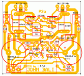
If you do not want to keep the trimmer on the board, it is a simple matter of laying the pin pattern of a resistor and trimmer on top of each other. This way you can do what Shaan suggests in his thread, use a trimmer at first, then remove and substitute a resistor later. I posted a pic of how I did that here (4th pic from the left, circled in red):
http://www.diyaudio.com/forums/solid-state/231662-peeceebee-38.html#post3487017
I think the rail caps are big enough now, just have to make a note of the series resistance. Low ESR can sometimes be better than high capacitance.
Btw, why is the Zobel cap so large?
If you do not want to keep the trimmer on the board, it is a simple matter of laying the pin pattern of a resistor and trimmer on top of each other. This way you can do what Shaan suggests in his thread, use a trimmer at first, then remove and substitute a resistor later. I posted a pic of how I did that here (4th pic from the left, circled in red):
http://www.diyaudio.com/forums/solid-state/231662-peeceebee-38.html#post3487017
I think the rail caps are big enough now
, just have to make a note of the series resistance. Low ESR can sometimes be better than high capacitance.Btw, why is the Zobel cap so large?
John,
see the empty space where P3a is printed?
That is where your Power Ground and +ve supply and -ve supply should be.
All grouped together to minimise loop area in the cables/traces and very close to the biggest current consumer on the PCB, the output devices.
It's here that the HF decoupling will connect direct to the output device power terminals and very close to the Power Ground.
For context, Doug Self has never claimed that his ultra-low distortion designs sound any better (or any different, for that matter) than merely low distortion designs. In their letter exchange, Peter Baxandall also emphasized that point.
If he never claimed that, what could be the possible reason for diy-er to build more complex circuit? Than it is just another exercise in electronics, and totally irrelevant for diy-ers.
Hi All,
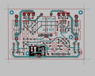
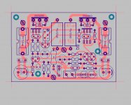
I just thought that I could also use some critiquing on my lay-out. It is to my knowledge a resemblance of the ESP lay-out, however I have never seen an actual board from ESP, this was a copy from a lay-out done by a member posted somewhere from the old P3A thread (could not remember who it was dv something??) . Anyway I have posted two images of my own version, and I have a question about the ground scheme of the zobel network and of the current source.
1st image, highlighted, current source ground goes to the star ground, zobel ground is tapped direct on the power ground.
2nd image, current source ground goes direct to power ground, zobel ground is tapped to the star ground.
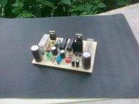
3rd image, a cheap shot how does it look like when assembled (not tested yet)
If my memory serves, I have read that the current source ground should be separated from the rest, also by placing a common heatsink for the drivers and the bias servo should improve thermal tracking (just like John Bali did in his version) not on my version. Another question, I have seen lay-outs that uses ground lifter (10ohms) but others do not have it. Is this necessary or is this just a matter of preference?, I understand this is CFP. Anyway is there something that I should worry about in my current lay-out?
Best Regards!
I just thought that I could also use some critiquing on my lay-out
. It is to my knowledge a resemblance of the ESP lay-out, however I have never seen an actual board from ESP, this was a copy from a lay-out done by a member posted somewhere from the old P3A thread (could not remember who it was dv something??) . Anyway I have posted two images of my own version, and I have a question about the ground scheme of the zobel network and of the current source.1st image, highlighted, current source ground goes to the star ground, zobel ground is tapped direct on the power ground.
2nd image, current source ground goes direct to power ground, zobel ground is tapped to the star ground.
3rd image, a cheap shot how does it look like when assembled (not tested yet
)If my memory serves, I have read that the current source ground should be separated from the rest, also by placing a common heatsink for the drivers and the bias servo should improve thermal tracking (just like John Bali did in his version) not on my version. Another question, I have seen lay-outs that uses ground lifter (10ohms) but others do not have it. Is this necessary or is this just a matter of preference?, I understand this is CFP. Anyway is there something that I should worry about in my current lay-out?
Best Regards!
Attachments
If he never claimed that, what could be the possible reason for diy-er to build more complex circuit? Than it is just another exercise in electronics, and totally irrelevant for diy-ers.
Hilarious comment, and very logical and reasonable........
However, it raises the issue; does a very low THD amp necessarily sound 'better', and in any case, what is 'better' anyway?
Hugh
@AKSA
Let me add some feedback on that ...As you all know i am in the repair thing and i repair amps ...a lot !! now days almost 600 per year and rising
obviously i repair almost anything that has transistors inside and preferably non European .
I can very well inform you that there is a range of costumers that eventhough has available proper amplifiers to listen from actually supports repairs and upgrades amplifiers that are on the other side
other side= single input transistor no LTP no current mirrors bootstrap probably Quasi and single rail supply ...
these people represent a 10-15% of my costumers and a variety of age ( that will mean non nostalgic old timers ) but also young people with experience on "proper" amplifiers
Still they find joy in the harmonic content of these specific high distortion and harmonics amplifiers ....
My article ""the G amp"" while G means Geriatric was based on that concept and was found not to have that much interest anyway http://www.diyaudio.com/forums/solid-state/229120-g-amp.html
Kind regards
Sakis,
I examined your amp. As I understand it all input and VAS sections are single ended, with a quasi output stage. The predominating harmonic will be high H2 at -65dB below fundamental, then around subsequent harmonics below 15dB reducing up to about H12.
This would be 'fruity, sweet and tubey'. Many would love this sound, although the specs would drive most away because they do not realise such a profile sounds so good.
This is the triumph of marketing over individual thought. Such is the world.......
Nice amp, congratulations!
Cheers,
Hugh
Last edited:
Hi AKSA
how are you would you say some critics to my layout please?
& I don't want to use any jumper. 250-400v rated will be fit there.
Thanks to your suggestion about elco & resistor//trimmer tricks
BTW I draw it long time ago & my PCB will not use any silkscreen
But your suggestion is good, I will try it
So if I do like what you say the power ground will be surrounding all the board's side, right? Ok we make it clear on next layout that I make
Regards
how are you
would you say some critics to my layout please?That cap so large because there are two tracks between it legs@John Bali: I will take a closer look later today, bit short of time right now.
I think the rail caps are big enough now
Btw, why is the Zobel cap so large?
& I don't want to use any jumper. 250-400v rated will be fit there.Thanks to your suggestion about elco & resistor//trimmer tricks
BTW I draw it long time ago & my PCB will not use any silkscreen
That reserved for small heat sink for the drivers & VBEJohn,
see the empty space where P3a is printed?
That is where your Power Ground and +ve supply and -ve supply should be.
All grouped together to minimise loop area in the cables/traces and very close to the biggest current consumer on the PCB, the output devices.
It's here that the HF decoupling will connect direct to the output device power terminals and very close to the Power Ground.
But your suggestion is good, I will try it
So if I do like what you say the power ground will be surrounding all the board's side, right? Ok we make it clear on next layout that I make
Regards
Last edited:
The Power Ground does not need to be connected to the Signal Ground by using PCB traces.
The Power Ground and the Signal Ground need to be referenced to the same voltage. This can be on board, or it can be off board.
If you are building more than one channel into your amplifier, then I assert that the Main Audio Ground (where Signal ground and Power Ground meet) must be off board.
The Power Ground and the Signal Ground need to be referenced to the same voltage. This can be on board, or it can be off board.
If you are building more than one channel into your amplifier, then I assert that the Main Audio Ground (where Signal ground and Power Ground meet) must be off board.
other side= single input transistor no LTP no current mirrors bootstrap probably Quasi and single rail supply ...
same fond memories here, i will revisit it in the near future when i can....
@John Bali:
Overall, the component placement looks pretty good,
Finding the best place to put the Zobel network, or any other output filter for that matter is usually awkward on a 2-layer board.
The 10R resistor should probably be rated at something over 1/4 watt (at least 1/2W, more depending on how much power you are designing for). This RC network will be in parallel with the speaker load, and it will see the same output voltage as the speaker. It will look like a high impedance at low frequency, and a low impedance at high frequency. (you can actually calculate impedance and estimate power at 60Hz and 20KHz)
So, wide pin spacing makes more sense for the resistor, than for the cap, and the resistor is the more likely component to bridge over a trace or two. You can also move the 10R on the other side of the trace that connects the 0R68 pairs, and avoid some of the problems. The 10R can bridge over the positive rail, and the cap will be normal size.
A good size rail cap on the board is a good idea, but 10,000uFd is probably overkill. I think you can shrink those a bit if you need room, and even if you do not, you could make a double pad pattern for smaller caps. From what I have seen testing my P3A, between 1000 and 2200uF would be enough for me. Obviously this depends on the main power supply, speakers, listening level, etc.
The same thing applies to the 4.7uFd input cap. There are capacitors with smaller dimensions that would work here just fine.
@PMI
ok thanks
The 10R & 3k3 they are 1/2 watt the others are 1/4 watt.
Zobel 104 & 10R is easily to swap just change the silkscreen.
Actually I more likely to make PCB layout as good looking to my taste even maybe not good enough for some reason.
Then when I make it I hope it just work, if not just redesign again/tweak it & I enjoy it at the end it works & you know how that feels
About 10mF elco, you're right it is too overkill I'll follow your 1000-2200uF.
Input caps also can be reduces or put it in other place (off board or jumper if sure our source is DC free)
Now there is some thinks inside my head, maybe I'll make a new layout for it
Btw it is good or not if we integrate power supply on the board ?
Dual mono maybe just better & if someone want to make it...
it's so simple just connect to transformer, input & output. Done...
"but it is not p3a anymore"
OT: I need to make my PeeCeeBee works now there something not normal there
so will not post here for a while see you
ok thanks
The 10R & 3k3 they are 1/2 watt the others are 1/4 watt.
Zobel 104 & 10R is easily to swap just change the silkscreen.
Actually I more likely to make PCB layout as good looking to my taste
even maybe not good enough for some reason. Then when I make it I hope it just work, if not just redesign again/tweak it & I enjoy it
at the end it works & you know how that feels About 10mF elco, you're right it is too overkill
I'll follow your 1000-2200uF. Input caps also can be reduces
or put it in other place (off board or jumper if sure our source is DC free)Now there is some thinks inside my head
, maybe I'll make a new layout for itBtw it is good or not if we integrate power supply on the board ?
Dual mono maybe just better
& if someone want to make it... it's so simple just connect to transformer, input & output. Done...
"but it is not p3a anymore"
OT: I need to make my PeeCeeBee works now there something not normal there
so will not post here for a while
see you
Last edited:
- Home
- Amplifiers
- Solid State
- Rod Elliot P3A Layout - Critics