Hi snake69fast,
The L25 is based on the L20 but as my thread indicates you should not read too much into the claimed specification. I doubt you would get anywhere near the claimed performance unless you power at the recommended voltage, around +/- 60V for the L20 (check recommended range). Even less so if you intend to use a digital SMPSU for powering, where you will have added high frequency switching noise to deal with. Your suggested system might work and might even sound passable but its probably not what most members of this forum would call "high fidelity". You would be better looking for a good amplifier module in the 10 - 50W range (possibly class A) where they have optimised the design for low distortion at low power rails and use a simple home-made linear power supply (transformer/rectifier/capacitor) to suit.
The L25 is based on the L20 but as my thread indicates you should not read too much into the claimed specification. I doubt you would get anywhere near the claimed performance unless you power at the recommended voltage, around +/- 60V for the L20 (check recommended range). Even less so if you intend to use a digital SMPSU for powering, where you will have added high frequency switching noise to deal with. Your suggested system might work and might even sound passable but its probably not what most members of this forum would call "high fidelity". You would be better looking for a good amplifier module in the 10 - 50W range (possibly class A) where they have optimised the design for low distortion at low power rails and use a simple home-made linear power supply (transformer/rectifier/capacitor) to suit.
Hi snake69fast,
The L25 is based on the L20 but as my thread indicates you should not read too much into the claimed specification. I doubt you would get anywhere near the claimed performance unless you power at the recommended voltage, around +/- 60V for the L20 (check recommended range). Even less so if you intend to use a digital SMPSU for powering, where you will have added high frequency switching noise to deal with. Your suggested system might work and might even sound passable but its probably not what most members of this forum would call "high fidelity". You would be better looking for a good amplifier module in the 10 - 50W range (possibly class A) where they have optimised the design for low distortion at low power rails and use a simple home-made linear power supply (transformer/rectifier/capacitor) to suit.
Thank you!
LJM L25 - the ultimate modifications
I had been listening to the modified L25 amplifier with my usual CD Coax source material but found it difficult to warm to the sound. The problem was I had previously listened to another amplifier in the same system and it had sounded significantly better in certain areas so I concluded that the L25 was still mediocre in terms of mid-range and high-end detail. Also, the sound stage seemed very narrow and really only between the speakers, with no real 3D depth and not beyond. I consulted Self and Cordell reference audio books, in particular their very detailed treatment of the Locanthi Triple EF output stage. As a result, I made a few simple changes that totally transformed the sound and lifted this amplifier to a much higher level musically. The changes are detailed here:
1) I used a solderless breadboard jig with two component clips to bridge the class A driver stages 100R 1W resistor. I could then add resistors in parallel to reduce the 100R value and increase the class A bias current. I added 100R initially (50R) and noticed a significant improvement in the bass and mid-range detail. Adding another 100R (33R) gained further improvement but now the top-end detail was also much better. I added a 2uF MKT speed-up capacitor across the 33R because it made the treble sound much more realistic and dynamic in my system (possibly optional depending on your own taste/overall amplifier system). This modification changed the original class A bias current from approx. 10mA to 30mA (3x greater)
2) Using same method above, I reduced the pre-driver class A bias resistor from 1K to 560R (approximately doubled current from 2mA to 4 mA). This change did not cause the two pre-driver transistors to heat excessively and they already have aluminium heatsinks fitted for better heat dissipation.
3) At the same time, I replaced the OPA604 op-amp with the much higher performance LME49710. The performance figures of this op-amp are truly exceptional, probably equalling or exceeding that of a discrete transistor ILP stage.
The moment I played the first CD on the new modified system I knew it had been transformed into a much better sounding amplifier. Clearly, the class A driver stages had not been optimally biased and this was evidenced from the rather suspicious circuit values of 1K and 100R. Though admittedly, LJM_LJM had designed the output stage for zero idle current bias and my early modification was to bias up to 25mA/transistor pair. This bias would reduce the class A bias current in the previous driver stages due to additional base current flow into the output transistors, to partially turn them on.
I am now extremely happy with these amplifier modules. Coupled with a decent high current power supply (+/- 60 VDC), they produce a very detailed and sonically engaging amplifier that's probably going to give me happy listening for several years to come or until I built an even better one") .
.
I had been listening to the modified L25 amplifier with my usual CD Coax source material but found it difficult to warm to the sound. The problem was I had previously listened to another amplifier in the same system and it had sounded significantly better in certain areas so I concluded that the L25 was still mediocre in terms of mid-range and high-end detail. Also, the sound stage seemed very narrow and really only between the speakers, with no real 3D depth and not beyond. I consulted Self and Cordell reference audio books, in particular their very detailed treatment of the Locanthi Triple EF output stage. As a result, I made a few simple changes that totally transformed the sound and lifted this amplifier to a much higher level musically. The changes are detailed here:
1) I used a solderless breadboard jig with two component clips to bridge the class A driver stages 100R 1W resistor. I could then add resistors in parallel to reduce the 100R value and increase the class A bias current. I added 100R initially (50R) and noticed a significant improvement in the bass and mid-range detail. Adding another 100R (33R) gained further improvement but now the top-end detail was also much better. I added a 2uF MKT speed-up capacitor across the 33R because it made the treble sound much more realistic and dynamic in my system (possibly optional depending on your own taste/overall amplifier system). This modification changed the original class A bias current from approx. 10mA to 30mA (3x greater)
2) Using same method above, I reduced the pre-driver class A bias resistor from 1K to 560R (approximately doubled current from 2mA to 4 mA). This change did not cause the two pre-driver transistors to heat excessively and they already have aluminium heatsinks fitted for better heat dissipation.
3) At the same time, I replaced the OPA604 op-amp with the much higher performance LME49710. The performance figures of this op-amp are truly exceptional, probably equalling or exceeding that of a discrete transistor ILP stage.
The moment I played the first CD on the new modified system I knew it had been transformed into a much better sounding amplifier. Clearly, the class A driver stages had not been optimally biased and this was evidenced from the rather suspicious circuit values of 1K and 100R. Though admittedly, LJM_LJM had designed the output stage for zero idle current bias and my early modification was to bias up to 25mA/transistor pair. This bias would reduce the class A bias current in the previous driver stages due to additional base current flow into the output transistors, to partially turn them on.
I am now extremely happy with these amplifier modules. Coupled with a decent high current power supply (+/- 60 VDC), they produce a very detailed and sonically engaging amplifier that's probably going to give me happy listening for several years to come or until I built an even better one
.
Last edited:
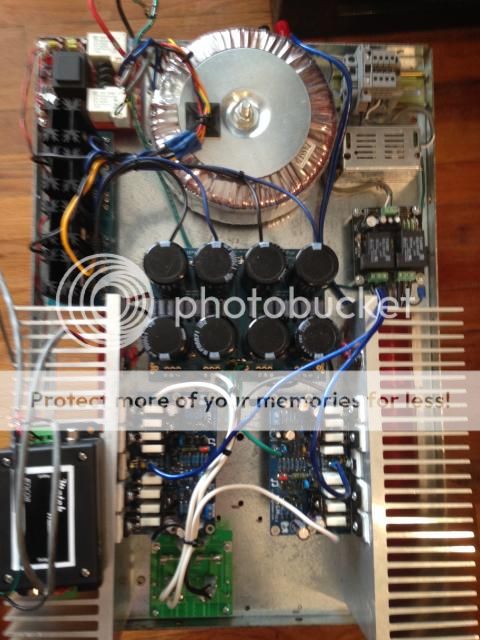
I assembled a pair of L20 boards that show to be version 9.2 and am pretty happy overall. I replaced the output devices with 2STC5948 and 2STA2120 and mounted to big heat sinks. I have a 1000VA torrid and loaded DC voltage is +-72V with 48,000uf capacitance on each the positive and negative rails. I am using these bridged mono as a subwoofer amplifier pushing a 4 ohm 18" sub and they are working great! I used a audio transformer from Edcor to get inverted signal and really am not sure the actual peak output but it has plenty of headroom to drive the sub for movies and has yet to get hot even when in music service with good death metal music playing very loud! Using a 7.2 ohm dummy load resistor I ran these in bridged mode for extended time with 0.5V 1KHz sine wave signal input and got clean 40V PK-PK output so a calculated output of over 220 watts. During the test I measured a little over 138 degrees F on the output transistors so did great even with constant high output but my dummy load resistor was much much hotter and had to turn it off to save the dummy load. Before setting up as permanent sub amp duty I ran these as stereo amplifier with music input and a old set of Norman Lab speakers. The amps sounded great to me with plenty of output power and no overheating problems. Overall for the price I am more than happy with the L20 and just received a second set of boards in the mail but the new boards are older ver. 9.0 instead of the 9.2 and will build and see how they sound.

What should I be doing with the output of these L20 modules, I assume it should have an RL network added? Any suggestions of components?
You do not need to output inductor. Unless your load is not sound, but a capacitor.
Is only the load capacitor, you only need output series inductance.
Or you sound box line more than 50 meters, sound box line and cib produce larger capacitance. More than 50 metres speakers line.
Normal household use. You don't need to inductance.
In addition. I opened the alibaba, I study all day, but I still don't know much about international express postage.
At present only in the operation of the test, or someone looking for me to buy? Laugh.
Analog amplifier - Acquista a poco prezzo Analog amplifier dai Fornitori Analog amplifier Cinesi a LJM AUDIO DIY su Aliexpress.com
L20V7 Is a super low distortion amplifier.
Its purchase address is here.
L20 V7 Audio Power Amplifier 2pcs Assembled Ultra Low Crossover Distortion | eBay
Its purchase address is here.
L20 V7 Audio Power Amplifier 2pcs Assembled Ultra Low Crossover Distortion | eBay
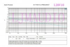
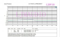
The latest test L20 The latest version.
THD +N< 0.0015% 50W 8R
THD+N <0.003% 50W 8R 20HZ-20 KHZ
2016-6-22
VER10. Has the strong driving ability.
THD +N< 0.0015% 50W 8R
THD+N <0.003% 50W 8R 20HZ-20 KHZ
2016-6-22
VER10. Has the strong driving ability.
Attachments
Last edited:
The latest test L20 The latest version.
THD +N< 0.0015% 50W 8R
THD+N <0.003% 50W 8R 20HZ-20 KHZ
2016-6-22
VER10. Has the strong driving ability.
Where can I buy L20 V10??

The latest test L20 The latest version.
THD +N< 0.0015% 50W 8R
THD+N <0.003% 50W 8R 20HZ-20 KHZ
2016-6-22
VER10. Has the strong driving ability.
LJM, Can you recommend a reputable supplier for L-20 v10? We read so much about bad quality products that give your (excellent) designs a bad name. Who can we trust to buy from?
Note: I tried to PM you, but your mailbox is overfull. I think others would be interested as well.
Thank you for your help.
Comment on well run in l20 v9.2
This is a belated reply to earlier posting.
"There is no need to touch any other components when the input coupling capacitor is removed. It just means that the the sound will improve and the LF responce will extend down to DC. If there is any DC on the input signal from the source then that would be a problen as the DC at the L20V9 speaker output terminal would no longer be zero and if more than 50mV then speaker damage could occur. My L20V9 PCB's have been working very well now for a couple of months. They are stock standard apart from removal of the input capacitor and they do not show any signs of instability. The heat sinks I am using are too big and don't get warm and it takes quite a few hours for the amps to sound nice at the top end. This might be because the output devices a running too cold or maybe not.*[/QUOTE]
Hmmm
I must admit that I normally have removed and shorted every dc blocking cap on amps for umpteen years.After finally get home and time to play my amps V9.2 I had been runnuig in for a few months I was pretty well shocked that the sonics were awful after bypass using silver wire. Shriller fatiguing with a bass roll off.
After several days I removed by pass to regain the performance and bass/midrange tonality. I normally HATE oscons in any part of any circuitry.
PS I havent yet installed the vishay bulk foil resistors yet..
I am sure something else is involved in the circuitry to produce such an adverse effect and I will probably try to find a smallish 10mf film capacitor to try .
It is a wonder why no firm produces such a product.Their is a great demand.
My amps also run pretty cool,I am using the 5 x heatsinks leftover from disaster L12s. Using 51 VDC 500watt tranny.
Curious.
Modifications of L25 for subwoofer amp.
Having reviewed this thread for info regarding modification of this thread in a subwoofer 'plate amp' build, I note recent comment regarding, input coupling, bandwidth and Q current modifications made here. More on this later.
My initial question relates to pitfalls in remotely relocating output transistors and their emitter resistors.
So, what I have is a L25 V2 - LJM 2004 - 2013
Appears to be all well and good visually, however I have application specific concerns that maybe addressed but the following modification.
Due to use of a reasonably large area heatsink [400mm x 300mm x 25mm] and not being constrained to enclosure size [plate amp inside subwoofer cabinet] has advantages and disadvantage as I see it regarding layout of all stages in the 'project' hence proposal to shift output transistors etc off the L25 board.
Reasoning being:
a) I don't need a compact [somewhat crammed] board and so,
b) I don't like the idea of 2 [total 8] output transistors 'back to back' mounted plus 3 driver transistors on a 126mm x 30mm x 30mm x 3mm aluminum angle then mounted on large area heatsink [contact area between angle and heatsink = 2780 sq mm]
Even with use of low thermal impedance compound between angle and sink I suspect I can do better, and note that other users have ditched the angle, folded out the subject transistors for mounting on heatsinks directly.
This maybe all well and good in a confined enclosure an attention to clearance between board and heatsink, however support of the now perpendicular board in a plate amp build is problematic [the way I propose layout].
c) Given the application [plate amp inside cabinet along with an 18" Driver as a subwoofer] I have concern regarding vibration G forces applied to components on board and as well as the rigid transistor legs. I'm well aware of copper work hardening [due to vibration fretting] even if driver board is well supported to consider this. More on this later regarding 'ruggedisation' modification.
d) At claimed output rating [500W at 4Ohms - 70V DC supply rails] the adequacy of pcb copper to conduct this current at low temp., even if this is dual layer construction.
Given the above points, I'm looking at options to relocate all output and driver transistors [total of 11 components] and the 8 emitter resistors mounted onto a simple pcb board that has brass busbar soldered to allow far higher current level than standard veroboard affords.
The flexable interconnect wires between Output and and Driver board being 30mm maximum length. Emitter / Collector wires larger gauge [1.5 sq mm CSA] and Base interconnect wire smaller [0.5 sq mm CSA]. The smaller Base wires is reasonable and allows for use of ferrite beads if there is a noise risk following extension.
This remote locating is intended to spread devices on heatsink and reduce vibration effects on transistor legs and the pcb board copper traces.
In doing this I see the potential to reduce interconnecting wires [given the Emitter resistors moved] common rails of the 8 output transistors - Yes?
I reason the less heat emitting devices on board the better for long term capacitor life and thermal stability.
SO..... is such a modification problematic in terms of 'noise risk' due to the, in essence, extension of transistor legs? Can this 'risk' if so, be ameliorated by use of less interconnect wires [common rails of 8 output transistors] and ferrite beads on Base interconnects and legs of the 3 driver transistors mounted on that angle.
More questions on:
a) the ruggedisation to follow and vibration risk to thenon-relocated 2 initial stage driver transistors with glued heatsinks,
b) bandwidth modification to limit at 1kHz.
c) merit in opamp modification recently posted by roklite at post #138 / #139 of this thread to suit my application.
d) need for gain control [10 - 25k pot. between L25 and line-in from feeder Amp]
.... to follow.
btw:
Input to L25: Yamaha RX-V1700 sub-out at 2V /1.2kOhm.
Driver load: 18" 8Ohm 600W
Target bandwidth: 18 - 500Hz
Hmmm
I must admit that I normally have removed and shorted every dc blocking cap on amps for umpteen years.After finally get home and time to play my amps V9.2 I had been runnuig in for a few months I was pretty well shocked that the sonics were awful after bypass using silver wire. Shriller fatiguing with a bass roll off.
It is a wonder why no firm produces such a product.Their is a great demand.
My amps also run pretty cool,I am using the 5 x heatsinks leftover from disaster L12s. Using 51 VDC 500watt tranny.
Curious.[/QUOTE]
WELL belated update as I have finally removed the Oscon type DC signal blocker and wired accross to obtain cleaner less coloured sound.
I have run this in for 100 hours plus and no problems but need to remove some of the graininess at very loud passeges (Very small) and want to revert to Silmics again for their nicer sound. Obviously easy first target is 47mf in the
current source side. C
I wish to increase this to 100uf. Any thougts as I already have these values lying around. I will later start the vishay resister replacements but I will no ONE step at a time. Anyone tried bypassing the cheapo 80v 150mf caps yet or any other ideas.It still running luke warm to cold.
Dave
update re L20 9.2
WELL belated update as I have finally removed the Oscon type DC signal blocker and wired accross to obtain cleaner less coloured sound.
I have run this in for 100 hours plus and no problems but need to remove some of the graininess at very loud passeges (Very small) and want to revert to Silmics again for their nicer sound. Obviously easy first target is 47mf in the
current source side. C
ONE step at a time. Anyone tried bypassing the cheapo 80v 150mf caps yet or any other ideas. It still running luke warm to cold. Except for a one hour seesion of Scrabin at tremendous levels. Maybe I should wire the short input signals direct to the board as the input block looks a little cheap and nasty.
Dave[/QUOTE]
Well several weeks on and the 47uf cap has been silmicized ? to nicer effect and I hope to by pass this with 47 nf polprop or similair soon.
After that it will be the Vishay Bulk foil resitors now my eyesight is returning to something near its normal. Soldering Iron out of mothballs.
I now have a lot more faith in the amps.
Only problem that seems to come and go is a slight buzzing which seems to be caused by having input or speaker terminal or mains leads near to each other.
Pretty soon the whole box will be permanantly sited in the rack and I can retire to just listening and disposing of all the bits Ive aquired on this journey..
Hope to post photos soon.
Dave
Well several weeks on and the 47uf cap has been silmicized ? to nicer effect and I hope to by pass this with 47 nf polprop or similair soon.WELL belated update as I have finally removed the Oscon type DC signal blocker and wired accross to obtain cleaner less coloured sound.
I have run this in for 100 hours plus and no problems but need to remove some of the graininess at very loud passeges (Very small) and want to revert to Silmics again for their nicer sound. Obviously easy first target is 47mf in the
current source side. C
ONE step at a time. Anyone tried bypassing the cheapo 80v 150mf caps yet or any other ideas. It still running luke warm to cold. Except for a one hour seesion of Scrabin at tremendous levels. Maybe I should wire the short input signals direct to the board as the input block looks a little cheap and nasty.
Dave
After that it will be the Vishay Bulk foil resitors now my eyesight is returning to something near its normal. Soldering Iron out of mothballs.
I now have a lot more faith in the amps.
Only problem that seems to come and go is a slight buzzing which seems to be caused by having input or speaker terminal or mains leads near to each other.
Pretty soon the whole box will be permanantly sited in the rack and I can retire to just listening and disposing of all the bits Ive aquired on this journey..
Hope to post photos soon.
Dave[/QUOTE]
Do not waist exspensive components it is not worth it.
Almost there ..
Hope to post photos soon.
Dave[/QUOTE]
Do not waist exspensive components it is not worth it.[/QUOTE]
I was hoping to have a positive scientific reply not an unqualified opinion that
contradicts 60 plus years of knowledge and experience including mods made to these boards by myself and others who have posted on this site.
Can someone with a technical background answer ,.. What are considered limitations of the design. ie weakest points? .For what its worth these boards have been quite robust considering their relocation several times within its case. Something that cannot be said about the other LJM versions Ive tried.
Expensive is a relative term and I have shedload of bits culled from my modiding years.Cannot even give most away but I am very familair with the sonic results that these parts can do when simply swapped.Certainly compared to bogstandard cheapo parts.
I even understand that on occasions a better part? will simply show up a weakest link somewhere else. ie sound worse ? This is absolutly true when Top quality resisters are inserted into a signal path. Other times the better part will just allow for future improvements. Hence a whole variety of opinions re mods?
This amp does have metalic sonic signature and its obvious why ?
Its is very cheap...Sadly I cannot eliminate all of it by using a pair of lower quality loudspeakers. So I am obliged to carry on for a short while.
Neither am I using a lossy CD system..Lt is a minimum of hirez 24/7.
Hope to post photos soon.
Dave
Do not waist exspensive components it is not worth it.[/QUOTE]
I was hoping to have a positive scientific reply not an unqualified opinion that
contradicts 60 plus years of knowledge and experience including mods made to these boards by myself and others who have posted on this site.
Can someone with a technical background answer ,.. What are considered limitations of the design. ie weakest points? .For what its worth these boards have been quite robust considering their relocation several times within its case. Something that cannot be said about the other LJM versions Ive tried.
Expensive is a relative term and I have shedload of bits culled from my modiding years.Cannot even give most away but I am very familair with the sonic results that these parts can do when simply swapped.Certainly compared to bogstandard cheapo parts.
I even understand that on occasions a better part? will simply show up a weakest link somewhere else. ie sound worse ? This is absolutly true when Top quality resisters are inserted into a signal path. Other times the better part will just allow for future improvements. Hence a whole variety of opinions re mods?
This amp does have metalic sonic signature and its obvious why ?
Its is very cheap...Sadly I cannot eliminate all of it by using a pair of lower quality loudspeakers. So I am obliged to carry on for a short while.
Neither am I using a lossy CD system..Lt is a minimum of hirez 24/7.[/QUOTE]
L 20 is not worth it. Other designs could be. I do a lot of mods. For L 7 I changed most of the resistors to Takman Carbon.
- Home
- Amplifiers
- Solid State
- L20 V8