Hard to follow...
Just a comment guys...
It becomes difficult to follow the thread when you accidentally 'cut' edit out the code at the start of what your quoting. see how the last closing code is still there? [/QUOTE] The initial code has the quote display in a field box, so avoiding confusion and provides a link back to quoted text... so we can read a partial quote in its full context.
Sorry to say..... interesting thread, interesting arguments and views on modification merit etc.... but becoming difficult to follow.
")
Just a comment guys...
It becomes difficult to follow the thread when you accidentally 'cut' edit out the code at the start of what your quoting. see how the last closing code is still there? [/QUOTE] The initial code has the quote display in a field box, so avoiding confusion and provides a link back to quoted text... so we can read a partial quote in its full context.
Sorry to say..... interesting thread, interesting arguments and views on modification merit etc.... but becoming difficult to follow.
Last edited:
End of the mods ? for now.
Sorry to say..... interesting thread, interesting arguments and views on modification merit etc.... but becoming difficult to follow.
[/QUOTE]
Well I have finally boxed up the near finished amplifier. Having Inserted a good few Vishay BULK FOIL caps in the signal path. Later this year I may return to mod and improve the others. I have decided against further cap changes apart from the pair of Silmics 47uf, and |silver wire accross dc blocking input cap as well as bypassing teflon/silver on DC power supplies from the bridge rectifier.
A few pieces of rfi absorbing material located near diodes etc.ie standard tried and tested mods..
As regards using any resisters with BRASS terminals in a serious circuit defies logic. A famous local saying about I would rather have by Backs*de rubbed with a housebrick comes to mind before using poor and diodic brass in a serious hifi circuit.Holco copper would have been much better choice but are still way short of the best.
Note , Even those plastic connecting joints shoud have the copper or silver wiring in direct connection before tightening down the screws.
All the testing was done with both sacd player and amp physically located on a floor IN FRONT of the powerfull loudspeakers. This is part of my historic way of testing for microfonic effects. They will soon be relocated in Townshend Seismic sink stand. Normally this produces even great 3d imaging,
The initial code has the quote display in a field box, so avoiding confusion and provides a link back to quoted text... so we can read a partial quote in its full context.Just a comment guys...
It becomes difficult to follow the thread when you accidentally 'cut' edit out the code at the start of what your quoting. see how the last closing code is still there?
Sorry to say..... interesting thread, interesting arguments and views on modification merit etc.... but becoming difficult to follow.
[/QUOTE]Well I have finally boxed up the near finished amplifier. Having Inserted a good few Vishay BULK FOIL caps in the signal path. Later this year I may return to mod and improve the others. I have decided against further cap changes apart from the pair of Silmics 47uf, and |silver wire accross dc blocking input cap as well as bypassing teflon/silver on DC power supplies from the bridge rectifier.
A few pieces of rfi absorbing material located near diodes etc.ie standard tried and tested mods..
As regards using any resisters with BRASS terminals in a serious circuit defies logic. A famous local saying about I would rather have by Backs*de rubbed with a housebrick comes to mind before using poor and diodic brass in a serious hifi circuit.Holco copper would have been much better choice but are still way short of the best.
Note , Even those plastic connecting joints shoud have the copper or silver wiring in direct connection before tightening down the screws.
All the testing was done with both sacd player and amp physically located on a floor IN FRONT of the powerfull loudspeakers. This is part of my historic way of testing for microfonic effects. They will soon be relocated in Townshend Seismic sink stand. Normally this produces even great 3d imaging,
its not difficult to follow if you are really interested ?
Sorry to say..... interesting thread, interesting arguments and views on modification merit etc.... but becoming difficult to follow.
[/QUOTE]
The reason for delating parts of the quote should be obvious.
The said response is ONLY to the parts that are relative to the reply.
It is not intended to provide easy reading for the causual onlooked but a direct reply to the posting...
The above is standard practice to replies WORLDWIDEand not just simplification of laziouness in a certain area of the above.
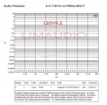
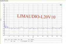
I am also going to respond to a chart showing low distortion posted today by designer LJM.
The chart is very interesting but after 55 years of, seeing , measuring and producing such items myself for various and sometimes obvious reasons. I must comment that they are really only usefull to me if they accompany a reason for such measurements. Ie Their is a noted sonic reason for the measurement. This should then be explained in the text. .
I point this out because there are quite a few of these various boards available worldwide and the measurements are meaningless unless you know the
quality of other factors.
Manufacturers of components and chips in particular often quote figures using laboratory isolated power supplies to get best results. These results vary wildly when used with rouge noisey supplies but I am not saying that this produces a worse result. just different and sometimes these colorations satisfy the consumers need. Hell , how many tube lovers would like the results of their microfonic tubes and micro temp changing compononts really published. Again it may be meaningless and will only satisfy the acadamic type cheerleaders I suspect.
In line with my histroric (slow) method on analysing componont changes in a methodic and simplistic way, I continued modifications to this excellent board especially trying to erradicate some sonic vageries.
Whilst I am still not totally sure of how each individual part sonically impinges on this circuit IT is now fairly obvious that the ElCaps supplied in the kits are of similair low quality sonically to the resistors fitted.
These produce IMO poor metalic dullish and grainy sonics including some ringing .. Even after longish run ins.
My favourite Silmics are difficult to fit as replacements on this smallish board and Panosonics (slimline 100v) seem to produce a solid not weedy sound.(hint)
I am almost finished upgrading most of the resistors to Vishay bulk foils. Yes this is now becoming an expensive board but possibly equaling and eventually beating any amplifier costing many many times more.
It is quite surprising where these replacements have created implovements.Not that I havent done this many times before. Even on early weaker LJM designs.
Sadly I will again have to wrap up development soon on this kit due to family issues and the need for a holiday.?
I have been considering the large ceramic 1 watt 10R resistor next.
On a previous amplifier design I by-passed the equivelant 2 watt version type Caddocks with a Vishay bulk foil to some small effect.
Note on this board I have slightly lifted the resistor from the board for improved heat potential.
I also noted somewhere in an earlier thread that it is possible that this output design might benefit from this being lower ??? than the 10R.
The only original elcap to replace is the 1000uf 10 volt.
Anyone got opinions on this part of the circuit ???
Dave
The initial code has the quote display in a field box, so avoiding confusion and provides a link back to quoted text... so we can read a partial quote in its full context.Just a comment guys...
It becomes difficult to follow the thread when you accidentally 'cut' edit out the code at the start of what your quoting. see how the last closing code is still there?
Sorry to say..... interesting thread, interesting arguments and views on modification merit etc.... but becoming difficult to follow.
[/QUOTE]The reason for delating parts of the quote should be obvious.
The said response is ONLY to the parts that are relative to the reply.
It is not intended to provide easy reading for the causual onlooked but a direct reply to the posting...
The above is standard practice to replies WORLDWIDEand not just simplification of laziouness in a certain area of the above.
I am also going to respond to a chart showing low distortion posted today by designer LJM.
The chart is very interesting but after 55 years of, seeing , measuring and producing such items myself for various and sometimes obvious reasons. I must comment that they are really only usefull to me if they accompany a reason for such measurements. Ie Their is a noted sonic reason for the measurement. This should then be explained in the text. .
I point this out because there are quite a few of these various boards available worldwide and the measurements are meaningless unless you know the
quality of other factors.
Manufacturers of components and chips in particular often quote figures using laboratory isolated power supplies to get best results. These results vary wildly when used with rouge noisey supplies but I am not saying that this produces a worse result. just different and sometimes these colorations satisfy the consumers need. Hell , how many tube lovers would like the results of their microfonic tubes and micro temp changing compononts really published. Again it may be meaningless and will only satisfy the acadamic type cheerleaders I suspect.
In line with my histroric (slow) method on analysing componont changes in a methodic and simplistic way, I continued modifications to this excellent board especially trying to erradicate some sonic vageries.
Whilst I am still not totally sure of how each individual part sonically impinges on this circuit IT is now fairly obvious that the ElCaps supplied in the kits are of similair low quality sonically to the resistors fitted.
These produce IMO poor metalic dullish and grainy sonics including some ringing .. Even after longish run ins.
My favourite Silmics are difficult to fit as replacements on this smallish board and Panosonics (slimline 100v) seem to produce a solid not weedy sound.(hint)
I am almost finished upgrading most of the resistors to Vishay bulk foils. Yes this is now becoming an expensive board but possibly equaling and eventually beating any amplifier costing many many times more.
It is quite surprising where these replacements have created implovements.Not that I havent done this many times before. Even on early weaker LJM designs.
Sadly I will again have to wrap up development soon on this kit due to family issues and the need for a holiday.?
I have been considering the large ceramic 1 watt 10R resistor next.
On a previous amplifier design I by-passed the equivelant 2 watt version type Caddocks with a Vishay bulk foil to some small effect.
Note on this board I have slightly lifted the resistor from the board for improved heat potential.
I also noted somewhere in an earlier thread that it is possible that this output design might benefit from this being lower ??? than the 10R.
The only original elcap to replace is the 1000uf 10 volt.
Anyone got opinions on this part of the circuit ???
Dave
Last edited:
Why did you again post, quoting me with code screwup? Can't you see that previous post is flawed and again today.... and leave it that way, without editing correcting.
It's not that hard to see where the error occurred. Review it!
You quoted me when there was an end code inserted half way through my post.... you made 'quick quote' and so the resulting flawed post. All it would take is editing the [\quote] code out, or change a character so it didn't effect a screwed up quote.
This is nothing to do with an "obvious" deletion of words not relevant you want to quote... in any case the postings of quotes are not displaying in windows due to simple code error that occurs when your haphazardly editing out words and including code... need this be explained?
Like, can you see the result.... and is it just lazyness to not fix it... or is it to annoy following a valid request to bother to quote and use the forum so threads can be understood easily when such quotes are made..... because it has been damn hard to make out where the quote is and where your comment starts earlier in this thread.
Frankly, it becomes easier to ignore the post you have made rather than try deciphering whatsit mean.
Jeeeeeeeezzzzzzzzzzzzzzzzzz.
The reason for delating parts of the quote should be obvious.
The said response is ONLY to the parts that are relative to the reply.
It is not intended to provide easy reading for the causual onlooked but a direct reply to the posting...
The above is standard practice to replies WORLDWIDEand not just simplification of laziouness in a certain area of the above.
So you say.. again could have corrected the code to have it clear whom said what. To not do isn't any 'standard' practice [confusion causing] I've seen... people actually try to make it clear in reply ESPECIALLY when quoting others so as to avoid misunderstanding, aside of making the post clear.
Who say what there? You know?
Why did you again post, quoting me with code screwup? Can't you see that previous post is flawed and again today.... and leave it that way, without editing correcting.
It's not that hard to see where the error occurred. Review it!
Says I...
Like, can you see the result.... take a look back, not just lat postings - take a look back through the tread.
Others don't do what you suggest is 'standard' practice. Need I cite examples?
Question remains; is it just lazyness to not fix it, or is it to annoy following a valid reasonable request to bother to quote and use the forum so threads can be understood easily when such quotes are made?
...because it has been damn hard to make out where the quote is and where your comment starts earlier in this thread. Could be easily fixed following review of what ya post and editing erroneous text or [/CODE]
Give it a rest, fellas. Stamping your feet over quotation protocols and the problems that many of our members may be having with writing English is not helpful. It is assumed here and in other forums, that when the thread has been hijacked or has drifted on to related matters, posts follow from the previous, unless otherwise shown by a reference, such as even a post #. If you must quote the text for clarity, at least enter the advanced reply option, trim the extraneous detail to the focus of your reply, a simple and easy step. FWIW, mercilessly full length, repeated and tedious quoting only irritates. If posts are well written and follow on as they should, you probably don't need them anyway.
To make it easier to follow this thread, 'better to read, edit and clean up your own spelling and punctuation before dictating to others what they should or shouldn't write. Set an example to yourself - at least clean text will lend a little credence to your message. If others then post between your reply and that which you are quoting, certainly an edit which adds a reference will be in order
To make it easier to follow this thread, 'better to read, edit and clean up your own spelling and punctuation before dictating to others what they should or shouldn't write. Set an example to yourself - at least clean text will lend a little credence to your message. If others then post between your reply and that which you are quoting, certainly an edit which adds a reference will be in order
Last edited:
In line with my continued histroric (slow) method on analysing componont changes in a methodic and simplistic way, I have continued modifications to these excellent boards especially trying to erradicate some now small sonic vageries.
Whilst I am still not totally sure of how each individual part sonically impinges on this circuit IT is now fairly obvious that the ElCaps supplied in the kits are of similair low quality sonically to the resistors fitted.
These produce IMO poor metalic dullish and grainy sonics including some ringing .. Even after longish run ins.
My favourite Silmics are difficult to fit as replacements on this smallish board and Panosonics (slimline 100v) seem to produce a solid not weedy sound.(hint)
I have finished upgrading most of the resistors to Vishay bulk foils. Yes this is now becoming an expensive board but possibly equaling and eventually beating any amplifier costing many many times more.
It is quite surprising where these replacements have created implovements.Not that I havent done this many times before. Even on early weaker LJM designs.
Sadly I will again have to wrap up development soon on this kit due to family issues and the need for a holiday.?
I have been considering the large ceramic 1 watt 10R resistor next.
On a previous amplifier design I by-passed the equivelant 2 watt version type Caddocks with a Vishay bulk foil to some small effect.
Note on this board I have slightly lifted the resistor from the board for improved heat potential.
I also noted somewhere in an earlier thread that it is possible that this output design might benefit from this being lower ??? than the 10R.
Maybe I misunderstood this 10R posting.
NOW.
The only original elcap to replace is the 1000uf 10 volt.
Anyone got opinions on this part of the circuit ???
I will now turn my attention to the few small value capacitors left as All but two metal film resistors have been replaced with vishay sfernice s102 type bulk foil.
Each change marginally improved sonics
The next elcap to be replaced is the 1000uf 10v with a Panosonic brand to try to remove the last vestigases of a very slight metalicness.
Previous use of tantalum caps has produced a similair type splashiness? but these orange types Value 105 look quite different to the old ones I hated.
I am looking at two options here. Remove both and replace with polyster or Polyprop either of which should sound smoother. OR
Bypassing both with a small value 10 or 100 nf polystyrene type.(easiest)
I think these these feed the 2n5551 amp stage.
Has anyone out there done anything similair to guild the lilly?..
I have to admit that these amplifier boards have proved totally reliable and trustworthy.
I have an Lm20 V9 amplifier and today I connected it according to http://www.diyaudio.com/forums/attachments/solid-state/406197d1394980052-l20-v8-l20-jpg The difference to the previous working setup was leaving GND board terminal unconnected as in picture. Now the board is dead. Previously I had GNG terminal connected both to speaker and GND of power supply and it worked. Any suggestion what might be broken?
In line with my continued histroric (slow) method on analysing componont changes in a methodic and simplistic way, I have continued modifications to these excellent boards especially trying to erradicate some now small sonic vageries.
Whilst I am still not totally sure of how each individual part sonically impinges on this circuit IT is now fairly obvious that the ElCaps supplied in the kits are of similair low quality sonically to the resistors fitted.
These produce IMO poor metalic dullish and grainy sonics including some ringing .. Even after longish run ins.
My favourite Silmics are difficult to fit as replacements on this smallish board and Panosonics (slimline 100v) seem to produce a solid not weedy sound.(hint)
I have finished upgrading most of the resistors to Vishay bulk foils. Yes this is now becoming an expensive board but possibly equaling and eventually beating any amplifier costing many many times more.
It is quite surprising where these replacements have created implovements.Not that I havent done this many times before. Even on early weaker LJM designs.
Sadly I will again have to wrap up development soon on this kit due to family issues and the need for a holiday.?
I have been considering the large ceramic 1 watt 10R resistor next.
On a previous amplifier design I by-passed the equivelant 2 watt version type Caddocks with a Vishay bulk foil to some small effect.
Note on this board I have slightly lifted the resistor from the board for improved heat potential.
I also noted somewhere in an earlier thread that it is possible that this output design might benefit from this being lower ??? than the 10R.
Maybe I misunderstood this 10R posting.
NOW.
The only original elcap to replace is the 1000uf 10 volt.
Anyone got opinions on this part of the circuit ???
I will now turn my attention to the few small value capacitors left as All but two metal film resistors have been replaced with vishay sfernice s102 type bulk foil.
Each change marginally improved sonics
The next elcap to be replaced is the 1000uf 10v with a Panosonic brand to try to remove the last vestigases of a very slight metalicness.
Previous use of tantalum caps has produced a similair type splashiness? but these orange types Value 105 look quite different to the old ones I hated.
I am looking at two options here. Remove both and replace with polyster or Polyprop either of which should sound smoother. OR
Bypassing both with a small value 10 or 100 nf polystyrene type.(easiest)
I think these these feed the 2n5551 amp stage.
Has anyone out there done anything similair to guild the lilly?..
I have to admit that these amplifier boards have proved totally reliable and trustworthy.
Perhaps a copper wire could be used. To replace the input capacitor
10UF
10V1000 UF can use oscon .
-----------------
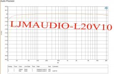
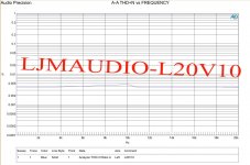
L20V9.2 is very stable. But it still makes me feel unsatisfied.
I made another version. But maybe they have different styles. Nor can it be a substitute.
VER10
It can only be a different style version. I'm not sure it will be better.
But I think it should be made. Because it has another sound that L20V9.2 does not have.
Its voice will be slower and its bass will be better.
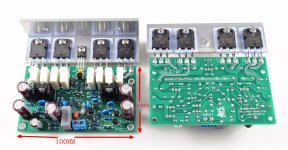
The main changes are as follows.
The output is changed from 3 to 2. This reduces the phase distortion and makes it more stable.
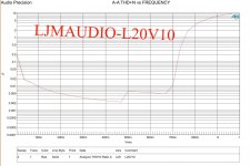
The input impedance increases. 27K input impedance allows us to use MKP 3.3 UF capacitors. And the low frequency did not decrease. 20HZ-0.15 DB
Use slower transistors. A42 A92. (But complex compensation capacitors are needed)
Used to reduce the feedback depth of the amplifier.
Distortion increased slightly. 0.004% THD+N
But it's still very low.
It can make the voice feel warmer.
Attachments
Last edited:
Just curious as to what has happened to the Version 10 board.
Ive not seen and sign of it on Ebay.
none available via search engine...
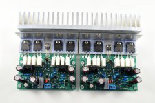
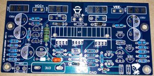
I do note that the picture ljp shows is on a green board ? Does this also mean that
green boarded version of all models are not pirated?
Sadly once again my nearly reliable L20 v9.2 boards failed yet again.
Now got 7 failed boards. Someone else has offered me more ???
I havent got the time to look into failures even with my eyesight restored
to resonable levels. Any takers ???
Ive not seen and sign of it on Ebay.
none available via search engine...
I do note that the picture ljp shows is on a green board ? Does this also mean that
green boarded version of all models are not pirated?
Sadly once again my nearly reliable L20 v9.2 boards failed yet again.
Now got 7 failed boards. Someone else has offered me more ???
I havent got the time to look into failures even with my eyesight restored
to resonable levels. Any takers ???
LJM L20 questions...
Just curious as to what has happened to the Version 10 board.
Ive not seen and sign of it on Ebay.
none available via search engine...
I do note that the picture ljp shows is on a green board ? Does this also mean that
green boarded version of all models are not pirated?
Sadly once again my nearly reliable L20 v9.2 boards failed yet again.
Hi
Just an update to say I have now seen the ver 10 boards for sale on Ebay in July 2019.
One is designed for a subwoofer only?.
As their is no answer from LJM himself re green boards it seems they are legit.?
Also in his last posting he confusingly states new board has reduced drivers from 3 to 2?
The latest pictures still show 8. Obvious difference is central location on board for signal inputs.
ps the failure of the boards was nothing to do with designs reliability.
V9.2 V10 are all sold versions.
I prefer V10.
In fact, these amplifiers are very stable. Many people in China have been using them for more than six years (V9.2)
But an amplifier circuit board. It's not a machine.
It is recommended to use the power filter I designed. And speaker protection.
Many unqualified products should be avoided as far as possible.
In China, I can repair all L20 for free. But in fact, in the last year. The number of damages is less than 2. Sales exceed 1000 quantities.
If you are very worried. Or not very familiar with DIY. I suggest you use L15D-SMD. If L20 is damaged. You can mail it to me. I can repair it free of charge.
The premise is that L-shaped aluminium must be used. And you can't change any components.
They are on Amazon Spain, not sure if they are bona fide: Q-BAIHE L20 Tarjeta de Amplificador de Potencia Amplificadores de Doble Canal 200W8R V10-2019: Amazon.es: Electronica
Does anyone else know of a reputable source for LJM amps? Is a bit of a jungle at the moment, with all these fake boards and counterfeit parts. It would also be good with a recommendation for a new set of amps. I already have some MX50 that work very well, but I need something more powerful in the order of 150W@8ohm
I think this should be genuine.
LJ L20 V10 Amplifier boards 200W 8 ohm mono (Pair) - Audiophonics
LJ L20 V10 Amplifier boards 200W 8 ohm mono (Pair) - Audiophonics
L20V7 Is a super low distortion amplifier.
Its purchase address is here.
L20 V7 Audio Power Amplifier 2pcs Assembled Ultra Low Crossover Distortion | eBay
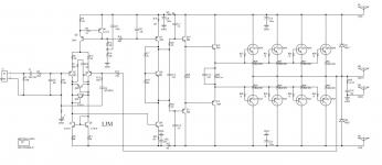
I just started to assemble my L20 V7 kit (see attached photo) however I just noticed that there is only one pair of 0.1 Ohm resistors for 8 output devices. For other L20 versions I noticed that there is the more expected four pairs of emitter resistors for the four pairs of output transistors.
I am concerned that the amplifier will fail/burn the output transistors without the emitter resistors. I noticed that the L20.5 also has eight resistors, one per output transistor.
What should I do? I am putting together this L20 V7 since the MX50x2 and MX50SE can't handle the transformer in the chassis I am using. I don't want this one to also blow the output transistors.
I also noticed that the schematic I found for V7 shows 8 resistors while the boards only have 2 resistors. (Also attached.) The schematic is obviously wrong and not for this output stage design.
Attachments
- Home
- Amplifiers
- Solid State
- L20 V8