Hi,
I'm new here and need help from all off you, I just developed my new pre amplifier circuit and already build it, but it is generate the frequency even when I short the input to ground.
The output dc offset is 2.8 mv and the oscillate frequency is 102 hz.
I tried every way to solve, but it is not better.
I also enclosed the circuit here.
I presume that you understand that the above is just a joke with a point ( though )
in a simple amplifier choise and matching of just one stage ...the LTP for example is very critical and use of unmatched parts might result to offset while closely matched parts will provide more punchy and tight bass with no offset .
in a circuit like the above which i cant understand the principal of operation but i can tell you for sure that looks like way too many areys of transitors are used and each and every one of them is an open door to paracistic oscilation...
That will be in simulation level cause if you try to do this in real life you will understand that a circuit like yours might also be very pcb demanting
slight mistake on the pcb and oscillation will be waiting arround the corner ....(unless you use the perfect transitors ...like the ones you have in your simulator )
just my opinion
Last edited:


Your schematic is too small for me to see the part numbering but you should improve your current sources to the LTPs. This 100 hz problem most probably is a powersupply or grounding problem. First incorporate supply decoupling like that used in Selfs blameless amplifiers to improve PSRR, also introduce a small resistor circa 47 to 68 ohms in series with the base of the current source transistor, if the current sources are oscilating this should put a stop to it.
")
let me tell you about a bug ..or a sikness that exists arround the people that design pcb and that will aso include me
when you design a pcb you need everything to look neat nice in place and order army parade style ...
well this is not always audiophile, distribution of earth is the major problem ...then distribution of power supply ...any mistake there and the singlest earth loop will of course create a buzz
Sorry again i am the last person to give opinion since i cannot follow your approach and i cannot understand the theory of operation of so many transistors involved in your circuit .
trust me though the small tips i am giving you apply either you have 4 transistors on the circuit or 24
kind regards sakis
Last edited:
Sakis, its quite easy actually - it is pretty much a dual LTP (with cascode) and VAS (with cascode). The chains of transistors are simply diode connected and create a voltage reference.
The regulator stage (no schematic shown) looks over complicated. A pair of LM317/337 is all you really need. It also looks like you've got large capacitors (1000uF) on the outputs of the regulators - DONT do that !
The regulator stage (no schematic shown) looks over complicated. A pair of LM317/337 is all you really need. It also looks like you've got large capacitors (1000uF) on the outputs of the regulators - DONT do that !
I very agreed with all of you that should it be power supply problem.
For grounding, the are dedicated star pcb lines for each of element.
I actually have 220uF+.01uf at very near by amplifier circuit but without series small value of resistor, so should it be good enough for ripple reduction? the power supply is applied 3 stages of LM317T.
So I'm doubt and no more idea now.
It also looks like you've got large capacitors (1000uF) on the outputs of the regulators - DONT do that !
At least not without putting a small series resistance in (0.3 - 0.5 ohms). Big cap = low esr. Big cap with low esr combined with output inductance of the reg = resonance within the audio band!
A small series resistance will damp the resonance.
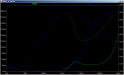
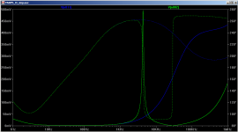
edit: attached sim showing output impedance with 1000uF output cap, green without any series resistance, blue with .3ohms series resistance.
edit2: second pic shows theoretically perfect 1000uF with no esr. first pic cap had 0.034 ohms esr in the cap model.
Tony.
Attachments
Last edited:
then again in the circuit there is only shown voltage of 15+15 volts ... what is the point of having six regulators on the power supply ?
are you feeding each stage with diferent regulator ? if so i dont think this good practice
Multiple stage of regulators can result better noise performance, I already tried with my another opamp based pre amp.
I can heard noise even take output from the first stage of regulator.
let me tell you about a bug ..or a sikness that exists arround the people that design pcb and that will aso include me
when you design a pcb you need everything to look neat nice in place and order army parade style ...
well this is not always audiophile, distribution of earth is the major problem ...then distribution of power supply ...any mistake there and the singlest earth loop will of course create a buzz
Sorry again i am the last person to give opinion since i cannot follow your approach and i cannot understand the theory of operation of so many transistors involved in your circuit .
trust me though the small tips i am giving you apply either you have 4 transistors on the circuit or 24
kind regards sakis
Yesterday I remove the transistor arrays you mention and replace them by 5v zener diodes, but the problem still exist.
I actually have 2 duplicated boards, so I try another one by removed cascode transistors out from both stages, so the result still the same with the previous one.
Distribution of earth. I have no idea how to test this one, each of ground pcb lines are quite shortly.
remove the regulators ... just for testing ...keep only one pair ...
Jaycee:
thanks for the explanation more or less this is what i had in mind Question is what is the benefit from it
similar circuits (not that complicated ) exists in many elektor schematics .... most of them was a nightmare when it comes to choise of parts( could only work with BC546 with hfe of 243.6 ) and then then a second nightmare to stabilize ....Giesberts was f**&*()@&! arround with us ..
to my understanding a death of zen if properly builted will kick the crap out of most of these circuits
- Status
- This old topic is closed. If you want to reopen this topic, contact a moderator using the "Report Post" button.
- Home
- Amplifiers
- Solid State
- Pre amp oscillate