Hi Tony,
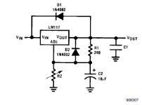
There is no capacitor at adj pin, it is a normal recommended circuit.
This sound card scope software is not absolutely like the normal scope.
Voltage and time range is not per div. it is for top-buttom and left to right.
for example:
Time = 100m then the 100ms is for from left to right.
So if volt = 2m then the actual volt/div = 2mv/20 = 0.1mv/div
Thus the ripple should be 0.6mv p-p. Is it acceptable?
I have ever done putting 0.47uF file cap in adj pin, so the output is not so stable for lm337.
5-10uf on adj pin should dramatically reduce ripple (on a 317) I've not used a 337. 0.47 is probably too low and may be why you got instability?
below is from the national datasheet
http://www.national.com/ds/LM/LM117.pdf
edit: I believe the scope software is per division, I've used the same software before") Try measuring a known ac voltage with your multimeter and compare the result on the scope to work out calibration
Try measuring a known ac voltage with your multimeter and compare the result on the scope to work out calibration
Tony.
below is from the national datasheet
http://www.national.com/ds/LM/LM117.pdf
edit: I believe the scope software is per division, I've used the same software before
Try measuring a known ac voltage with your multimeter and compare the result on the scope to work out calibration Tony.
Attachments
Last edited:
Thank you so much to Joycee for what you have done simulation.
It is interesting why the negative feedback became a positive feedback in the simulation.
There is a saying - oscillators amplify, and amplifiers oscillate
Closed loop gain and phase are important in any amplifier design. Phase margin - Wikipedia, the free encyclopediaWhat about V4 stand for?
This is just a node in the simulator that is used when an AC analysis is done. During normal transient analysis, this node has no effect.
The oscillated frequency is about 12Mhz that a high frequency oscillation, but I have now followed your suggestion regarding change the capacitance.
What else I should do next. please advise.
I think your remaining problem is power supply related. I have only briefly looked at posts since... but i would say that the 3-stage regulation is a problem. Test the circuit with an ordinary 1-stage regulator and see what happens.
If you really want extra regulation - i am assuming you wish to minimise noise here - look at the Jung super regulator. Or you could try a capacitive multiplier before a single LM317/337. Definitely bypass the LM317/337's Adjust pin as shown in the datasheet - the improvement in noise is significant.
And yes - you really need a 'scope
I have only just got one myself, a Tektronix 2213A - and it is indispensable. It really is a whole new ball game when you can see waveforms. Take a look at eBay and just look for a 20MHz dual channel old-fashioned CRT type oscilloscope - they're quite affordable.
Last edited:
Hi All,
During my giving up, I got solved now.
It is actually not oscillation and power supply problem.
I can't believe it.
It is the grounding issue.
There are most of the ground pcb lines are shared with the power supply main ground.
I changed the ground connection position with a bit modified. Now the problem gone.
100hz output reduced to micro volt level and when even connected to power amp. it is quite quiet at lound speaker
Now I'm on test listen the music.
unfortunately I got delivered of LME49713H current feedback low THD Opamp, then have to create 2 more boards to compare the sound quality between discrete circuit and IC.
Thank you to All of you for the best efforts.
well done then .... now you may add 2.000-3.000 arrays of bc more
It is now zener diode.
I would like to know which one better lower noise.
Transistor. (expensive and complex)
LED. (a bit more easier and lighten in chassis)
Zener. diode (more and more easier)
resistor network(considering)
That it Tony, the return current between signal and power are totally difference. Fortunately it is just pre amp, in case of power amp, we have to be careful more..Well done and a valuable lesson about grounding layout! I assume that some of your signal ground was shared with some higher current return. Good to hear it's sorted!
Tony.
It is my lessen learnt too.
Thanks for your contribution. and this forum.
- Status
- This old topic is closed. If you want to reopen this topic, contact a moderator using the "Report Post" button.
- Home
- Amplifiers
- Solid State
- Pre amp oscillate