smithomo, do you have scope output pictures for the 102Hz noise? could you post them? Seeing the waveform shape might help in troubleshooting.
It looks from the pictures that this is not mounted in any case, so I guess it is unlikely you have an earth loop from input to output?
Tony.
It looks from the pictures that this is not mounted in any case, so I guess it is unlikely you have an earth loop from input to output?
Tony.
remove the regulators ... just for testing ...keep only one pair ...
Jaycee:
thanks for the explanation more or less this is what i had in mind Question is what is the benefit from it
similar circuits (not that complicated ) exists in many elektor schematics .... most of them was a nightmare when it comes to choise of parts( could only work with BC546 with hfe of 243.6 ) and then then a second nightmare to stabilize ....Giesberts was f**&*()@&! arround with us ..
to my understanding a death of zen if properly builted will kick the crap out of most of these circuits
Ok I will try, but I'm already take this power supply output used for another opamp base preamp. it is ok no problem.
My 3 stages are working to as step down the voltage from the rectifier (3000 uf totally) 21V ---> 18V->>16V-->15V.
By the way I missed to tell all of you the transistors are 2 no. BC550B and BC560B.
The measure hfe is about 350 -490.
Hi wintermute,smithomo, do you have scope output pictures for the 102Hz noise? could you post them? Seeing the waveform shape might help in troubleshooting.
It looks from the pictures that this is not mounted in any case, so I guess it is unlikely you have an earth loop from input to output?
Tony.
I unfortunately have no oscilloscope, I measure it from my digital multimeter (HZ) I don't know is it accurate enough, but what I heard from loud speaker should be that frequency.
BTW, i simulated the design as shown and it oscillates horribly. I think you have the Miller capacitors wrong on the schematic - they should connect from base of Q11 to collector of Q13 and base of Q35 to collector of Q37 respectively.
It is the correct already, I'm ever have this kind of cascode on my another DIY power amplifier.
What is the tool you used for simulation, my protel simulation look very fine.
I'm thinking about the grounding problem, but in my designed pcb, all elements have their own line(star topology), so what else still not yet considered.
1. power supply ripply (tested with another opamp preamp then working ok.)
2. Ground loop (no because of "star".)
3. EMI from transformer.(I put toroidal transformer 50 cm away from circuit.)
4. oscillation from cascode circuit.(not better even when bypass it.)
5. Too long AC cable length from transformer(already tried and then not better.)
6. My bad circuit design.(please kindly advise.)
Hi Smithomo,
firstly I'd say revisit Jaycee's post 15 the fact that when he simmed it it oscillated tends to indicate it is a design problem.
Outside of that I'd say 1, 4 or 6 are the most likely.
The reason I wanted to see the waveform is that power-supply related 100Hz ripple has a pretty distinctive look.
I'm leaning away from 2 and 3 because of the 100Hz frequency, similarly for 5. by elimination that leaves 1, 4 and 6") 4 I don't know as my amp design knowledge is very minimal, similarly for 6 I can't comment
4 I don't know as my amp design knowledge is very minimal, similarly for 6 I can't comment
Tony.
firstly I'd say revisit Jaycee's post 15 the fact that when he simmed it it oscillated tends to indicate it is a design problem.
Outside of that I'd say 1, 4 or 6 are the most likely.
The reason I wanted to see the waveform is that power-supply related 100Hz ripple has a pretty distinctive look.
I'm leaning away from 2 and 3 because of the 100Hz frequency, similarly for 5. by elimination that leaves 1, 4 and 6
4 I don't know as my amp design knowledge is very minimal, similarly for 6 I can't comment Tony.
If youre measuring ti with a meter's counter function, these are not usually much good over a few KHz, so it is probably telling you about the MHz oscillation I see in the simulator. Try changing the compensation capacitor connections as I suggested - this makes the circuit stable in the sim.
Bear in mind also that this arrangement has a high gain bandwidth - 1.5MHz in the sim. That is going to cause you real life issues without good decoupling and layout. Increasing the Miller capacitors to 47pF makes this a bit more reasonable 600KHz.
Regulators - if one stage of LM317/337 is not enough, look at the Jung super regulator.
Hi jaycee and All,
Thank you for the suggestion, I have already tried to increase the compensation capacitor(feedback path) now from 5pf to 61 pf, and then C20 and C26 now change from 20pf to 45pf, but unfortunately still not better.
I eventually used the pc oscilloscope to capture the waveform then here we are please kindly analyse this.

Time/div= 35mS
Amplitude=9mV/Div
Thank you for the suggestion, I have already tried to increase the compensation capacitor(feedback path) now from 5pf to 61 pf, and then C20 and C26 now change from 20pf to 45pf, but unfortunately still not better.
I eventually used the pc oscilloscope to capture the waveform then here we are please kindly analyse this.
Time/div= 35mS
Amplitude=9mV/Div
Well, that certainly doesn't look like any waveform I've seen on the output of something I've been testing! However it looks like the frequency is around 120 Hz. Is your mains 60 Hz?
Tony.
Hi Tony,
It is 50Hz power line.
Have you thinking about power supply impedance problem?
I really have no experience about this kind oscillation.
That sort of waveform would suggest the -ve rail is has a problem. The LM337 is more twitchy than the LM317. I would say you need to work out where the problem is - in the power supply or the preamp circuit.
I'd suggest disconnecting your onboard regulator circuit and powering the preamp from a conventionally made +/-15V supply, such as a single LM317/337 or 7815/7915 for testing. You will probably need to change the decoupling capacitors to do this - I would use 100n-470n polyester or ceramic for C14/C28, and some good quality 220-470uF electrolytics for C15/C29.
BTW I used LTSpice to simulate the circuit.
Some simulation details:
You can see how the bandwidth shows lack of any compensation here. Note the phase too, negative feedback turned into positive. This is the result (with input = 0v)
The only way you'll see that sort of oscillation for real, is with a real 'scope. A sound card will not pick it up, and you will typically notice it as poor sound and most likely the transistors will get hot.
Now again with the "correct" method of Miller compensation:
This is more reasonable - the 0dB point is 1.2MHz and the phase does not drop below 90. However this would take a really good layout to achieve in real life... and it's totally unneccesary for audio. With the Miller capacitors at 47pF we get this:
Much more reasonable at 600KHz. Shouldn't be a problem.
You'll note I used LED's for the cascodes - having checked with the diode-connected transistor stacks you have used, the results are the same - the LED's are just simpler to implement. A green LED will drop 1.7V so two of them give pretty similar voltages. I also decreased their feed resistors to give about 2.5mA through them to obtain a stable reference. I'd suggest the same thing with the transistors if you wish to keep them.
An externally hosted image should be here but it was not working when we last tested it.
An externally hosted image should be here but it was not working when we last tested it.
You can see how the bandwidth shows lack of any compensation here. Note the phase too, negative feedback turned into positive. This is the result (with input = 0v)
An externally hosted image should be here but it was not working when we last tested it.
The only way you'll see that sort of oscillation for real, is with a real 'scope. A sound card will not pick it up, and you will typically notice it as poor sound and most likely the transistors will get hot.
Now again with the "correct" method of Miller compensation:
An externally hosted image should be here but it was not working when we last tested it.
An externally hosted image should be here but it was not working when we last tested it.
This is more reasonable - the 0dB point is 1.2MHz and the phase does not drop below 90. However this would take a really good layout to achieve in real life... and it's totally unneccesary for audio. With the Miller capacitors at 47pF we get this:
An externally hosted image should be here but it was not working when we last tested it.
Much more reasonable at 600KHz. Shouldn't be a problem.
You'll note I used LED's for the cascodes - having checked with the diode-connected transistor stacks you have used, the results are the same - the LED's are just simpler to implement. A green LED will drop 1.7V so two of them give pretty similar voltages. I also decreased their feed resistors to give about 2.5mA through them to obtain a stable reference. I'd suggest the same thing with the transistors if you wish to keep them.
Hi Tony,
It is 50Hz power line.
Have you thinking about power supply impedance problem?
I really have no experience about this kind oscillation.
Hi Smithomo , Rectification pulses are twice the mains frequency with a full wave rectifier. Actually I've looked at your waveform again and if I use the part of the waveform at 0 time and then look again at 30ms it is actually 100Hz not 120 as I thought.
I would put the scope probe (assuming you have something between the probe and the soundcard) on the +ve and -ve rails of the powersupply and see what you get. If you don't have a buffer circuit between the soundcard and the probe put a 10uF film or bipolar cap in between. Both should be dead flat.
Tony.
edit: I was wrong, I have seen a waveform like that on the output of something I was testing
http://www.diyaudio.com/forums/soli...oing-here-much-head-banging-2.html#post693838 and to save having to wade through the whole thread the final resolution http://www.diyaudio.com/forums/soli...oing-here-much-head-banging-3.html#post697224
Last edited:
My 3 stages are working to as step down the voltage from the rectifier (3000 uf totally) 21V ---> 18V->>16V-->15V.
Sometimes too much is not enough.
This cannot work if you are using LM3x7 regulators.
18->16V is borderline.
16->15V requires LDO regulators.
Is the 21V the average, peak, or bottom of the DC after ripple?
One stage 21V->15V might solve your problem.
That sort of waveform would suggest the -ve rail is has a problem. The LM337 is more twitchy than the LM317. I would say you need to work out where the problem is - in the power supply or the preamp circuit.
I'd suggest disconnecting your onboard regulator circuit and powering the preamp from a conventionally made +/-15V supply, such as a single LM317/337 or 7815/7915 for testing. You will probably need to change the decoupling capacitors to do this - I would use 100n-470n polyester or ceramic for C14/C28, and some good quality 220-470uF electrolytics for C15/C29.
BTW I used LTSpice to simulate the circuit.
Hi All,
Ok I just tried to measure again by sound card oscilloscope. Considering to invest a real oscilloscope I'm thinking.
So this is the dc output from my current +15V regulator(a 22uF electrolyte capacitor is taken for this measurement)

and then -15V regulator

Now as suggestions to take one 1 stage regulator, so I take out others
then here is +15 single regulator

and -15 single regulator

So now the outcome is still not better.
This is for output waveform.

About the power supply, I have 1 ohm and 220uf,0.1uF for decoupling, so now I thought power supply is not the issue now.
Thank you so much to Joycee for what you have done simulation.
It is interesting why the negative feedback became a positive feedback in the simulation.
What about V4 stand for?
The oscillated frequency is about 12Mhz that a high frequency oscillation, but I have now followed your suggestion regarding change the capacitance.
What else I should do next. please advise.
Sometimes too much is not enough.
This cannot work if you are using LM3x7 regulators.
18->16V is borderline.
16->15V requires LDO regulators.
Is the 21V the average, peak, or bottom of the DC after ripple?
One stage 21V->15V might solve your problem.
21V is the average voltage measurable from multimeter.
Hi Smithomo, if I'm not mistaken, that is showing almost 12mv P2P ripple on the output of your regs? That seems awfully high to me. How much current is your preamp drawing?
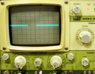
first pic is the output of my LM317 reg circuit (on breadboard and was picking up rf in the Mhz range hence the general noise) scope was set to 2mV/ division. Load was 125mA (purely resistive).
The second pic is the input to the reg, the scope was also set at 2mV / div there is a CRCRC before the reg.
Can you post the circuit diagram for your reg circuit? do you have an adj pin bypass cap?
Tony.
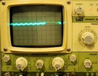
Attachments
Last edited:
- Status
- This old topic is closed. If you want to reopen this topic, contact a moderator using the "Report Post" button.
- Home
- Amplifiers
- Solid State
- Pre amp oscillate