Hi abetir,
What paper did you use to transfer the toner in the pcb?
Regards,
Boyet
Ideally ( some) people use printer photo paper . But there are several types and you should be sure you are printing on the correct side. Some low cost photo paper works very well.
Next best inexpensive option is shiny paper used to print leaflets for products/promotional brochures and glossy magazine pages. The paper should not be too thin.
You will need to test the paper. If it works well and comes from a glossy magazine then reserve it for all your pcb printing needs !
")
Paper should be typically 70 to 80 gsm ( like most paper used for normal printing).
Nothing is cast in stone. Try out what ever is available. Something will work !
Nothing stops you to assemble on the copper side, it will work as well and anybody looking inside your box would think it is double sided.Perfect DIY...well almost...

Nothing stops you to assemble on the copper side, it will work as well and anybody looking inside your box would think it is double sided.


Do anybody thoughts deeply change the way sounds your system ?Nothing stops you to assemble on the copper side, it will work as well and anybody looking inside your box would think it is double sided.
..pretty close Shaan..
It's actually an A4 copy paper wrap.
boyet,
I was told the A4 size stickers being sold at National Bookstore is ideal for use on toner transfer method (you won't be needing the sticker of course just take the "backing paper"), better yet check on the "Staples" brand. I dunno' if you can find the "wrapper" that I've used, it was actually for office use, but I guess any glossy type paper that can tolerate heat without peeling off, should be good enough for the job.
In laserjet toner transfer method, "practice makes perfect"
Hi abetir,
Thank you for the info. I will checked on the National Bookstore your recommendation. Thanks Again.
Regards,
Boyet
Ideally ( some) people use printer photo paper . But there are several types and you should be sure you are printing on the correct side. Some low cost photo paper works very well.
Next best inexpensive option is shiny paper used to print leaflets for products/promotional brochures and glossy magazine pages. The paper should not be too thin.
You will need to test the paper. If it works well and comes from a glossy magazine then reserve it for all your pcb printing needs !
Paper should be typically 70 to 80 gsm ( like most paper used for normal printing).
Nothing is cast in stone. Try out what ever is available. Something will work !
Hi ashok,
Thank you for answering my query.
Regards,
Boyet
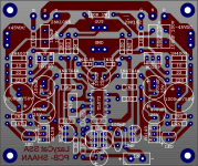
Shaan, please fix bd 139/140 silkscreen component (rectangular symbol for metal surface) , for skilled builder this is easy but for newbie like me this will make hell...this happen to me. Wrong ECB pin just by following bd139/140 silkscreen componentThis is my plan. Please comment...
Hi naf.
The only problem I think is when one doesn't know the pin alignments of the TO126 package, which happened in your case too. That is why I pointed the "E C B" to each of them. Knowing the pins of the BJTs is a basic requirement and I think if one places the transistors following the E C B as situated in the silkscreen then all will be well.
The rectangular symbol is for TO220 not TO126 coz my stupid PCB software don't have it. The picture is just to show what the final think will look like. I will remove the rectangles in the final version(which I am going to build myself too).
Thanks you, ShaanHi naf.
The only problem I think is when one doesn't know the pin alignments of the TO126 package, which happened in your case too. That is why I pointed the "E C B" to each of them. Knowing the pins of the BJTs is a basic requirement and I think if one places the transistors following the E C B as situated in the silkscreen then all will be well.
The rectangular symbol is for TO220 not TO126 coz my stupid PCB software don't have it. The picture is just to show what the final think will look like. I will remove the rectangles in the final version(which I am going to build myself too).
does this servo version have been tested and Ok?
I'm waiting your result... and preparing my ironSo far okay in sim only. I am currently soldering the IC and the others parts and will connect them hanging over my SSA. I am going to order a bunch of the servo peeceebee within a week or two.
.Glad to hear that you will order a bunch of the servo peeceebe

hai shaan howare today....very nice your layout ssa pcbHi naf.
The only problem I think is when one doesn't know the pin alignments of the TO126 package, which happened in your case too. That is why I pointed the "E C B" to each of them. Knowing the pins of the BJTs is a basic requirement and I think if one places the transistors following the E C B as situated in the silkscreen then all will be well.
The rectangular symbol is for TO220 not TO126 coz my stupid PCB software don't have it. The picture is just to show what the final think will look like. I will remove the rectangles in the final version(which I am going to build myself too).
Everybody knows that it would work...
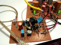
Test done. Offset +/-2mV. Opamp fed directly from Zeners(I know this is not good, that's why there will be cap-multipliers in the servo peeceebee).
Cheers!
shaan
p.s.- my veroboard SSA has become super ugly. Sorry for the bad looks!
edit:- 1. no sonic/bias change, 2. the pots are disconnected from the inputs.
I'm waiting your result...
Test done. Offset +/-2mV. Opamp fed directly from Zeners(I know this is not good, that's why there will be cap-multipliers in the servo peeceebee
).Cheers!
shaan
p.s.- my veroboard SSA has become super ugly. Sorry for the bad looks!
edit:- 1. no sonic/bias change, 2. the pots are disconnected from the inputs.
Attachments
Last edited:
May-be it would be carefull to short circuit the unused outout OpAmp with its - input and + input to ground ?Please comment...
With no feedback, the OP Amp has terrific full gain (noise) and can oscillate With negative effects, both by capacitive coupling with the other one and its power supply rails. Just plug your oscillo to the unused output pin as it is...Hi Christophe.
Yes I can do it.
Would you please explain the advantage? I don't know what bad would happen if the unused channel is left floating?
.Did-you imagine to let your power amp with no feedback ? It is the same.
This is my plan. Please comment...
Hi Shaan,
Can you please point to the schematic corresponding to your last art work?
BTW, very nice layout.
Tony
With no feedback, the OP Amp has terrific full gain (noise) and can oscillate With negative effects, both by capacitive coupling with the other one and its power supply rails. Just plug your oscillo to the unused output pin as it is...
.Did-you imagine to let your power amp with no feedback ? It is the same.
Thanks a TON for the explanation!
Unused inputs shorted to ground.
- Status
- This old topic is closed. If you want to reopen this topic, contact a moderator using the "Report Post" button.
- Home
- Amplifiers
- Solid State
- Simple Symetrical Amplifier