On my amp, i used a big toroidal trasfo (1100 VA), and big caps. Adding this cap multiplier had changed the sound in an incredible way to the top:
http://www.esperado.fr/images/stories/SSA-Crescendo/supply.gif
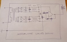
In the diagram you post you still have the earth lead - which is connected to most sensitive places throughout your entire audio system - connected directly to the transformer secondaries which will resonate violently at a very high frequency every time the diodes switch off - and this resonance can carry on continuously in between each diode switch off - so the secondaries are resonating at very high frequency all the time !
I cannot imagine that any amount of capacitor multiplication will entirely eradicate this noise so I would personally not use or recommend this kind of supply.
")
Last edited:
Using two LT3092 in serial ? They afford 40v 200ma.I have not yet found a solution to replace the r380 by a current source
Despite it is very classical, exactly equal to a simple bridge used with a single secondary coil and working perfectly with no significant noise ?I would personally not use or recommend this kind of supply.
If you are aware of switching peaks, use fast switching diodes and an accurate ground wiring. Plus some film caps. And remember a diode is too a hf demodulator.
Aware more of all the hf parasitics carried by the ac outlet.
YO People!
Problem solved. Hum gone.
Changed the zener-parallel capacitor to 2200uF. Clean and clear.
Makes me think... 1000uF capacitors would be enough here. Those caps must be either leaky or fake. Whatever.
I'm Happy again.

edit:- I recall that last year I faced the same problem with SSA, but more severely. Maybe the grounding was bad or something; and I used only gain of 10(too low?). Probably there was oscillation too. Anyway, life is good now.
Problem solved. Hum gone.
Changed the zener-parallel capacitor to 2200uF. Clean and clear.
Makes me think... 1000uF capacitors would be enough here. Those caps must be either leaky or fake. Whatever.
I'm Happy again.
edit:- I recall that last year I faced the same problem with SSA, but more severely. Maybe the grounding was bad or something; and I used only gain of 10(too low?). Probably there was oscillation too. Anyway, life is good now.
Last edited:
Despite it is very classical, exactly equal to a simple bridge used with a single secondary coil and working perfectly with no significant noise ?
If you are aware of switching peaks, use fast switching diodes and an accurate ground wiring. Plus some film caps. And remember a diode is too a hf demodulator.
Aware more of all the hf parasitics carried by the ac outlet.
Yes, very classic, as are many types of power schemes & regulators - but they nearly all seem to focus on the noise on the rails.
My experience is that no matter how good the regulators in series with the power rails are there are still audible gains to be had by filtering the noise on the earth rail even with ALL the measures you prescribe above plus others you don't mention.
And so do i ;-) My purpose, posting this schematic was about the regulation, not RC snubbers theory.Yes, very classic, as are many types of power schemes & regulators - but they nearly all seem to focus on the noise on the rails.
What do you prefer, parallel the 2 coils an use 2 bridges ?
I had tried the two, and really found no difference, both on the rails to ground and the ground leakages to the earth, apart the little power consumption outlet side, at rest, due to the slight voltage difference between the 2 coils.
On my side, i worry about hf transmitted by capacitive coupling between the coils and coils to chassis, not about any supposed tension with NO current to any reference, that snake oil can cure. (no change to use one or two serial switches in a closed loop).
Please, can-you post schematic of what you think a better solution from AC ?
I (and others, i presume) would be very graceful to learn something (i'm serious).
Last edited:
To make the things clear (i do not like fog or smoke) concerning power supply, my "fast switching" allusion was, of course, a joke.
Any Diode in a bridge is fast enough with a 50 or 60 Hz AC. And the fastest, the hightest will be the "ring" at the switching off of the diodes.
Some would like, on the contrary, to use little parallel caps with each diode to slow them and smooth the switching..
Of course, you will like to add a EMI filter before the trasfo's primary, direct in the AC inlet of the amp.
And RC snubbers as a charge connected to the secondary coils to help dumping the switching noise.
As each particular situation (AC voltage, trasfo, charge etc.) request snubber tuning, my purpose was not to talk about that part of a PSU design. Nor recommend to use the values of this schematic to power a +-25V amp ;-)
Last edited:
Well, cher Christophe, since nobody accepts the glove, I will tell one of my tricks, even if heaven knows that I am the least qualified to do so...but somehow I just cannot build stock PSs; I always have to try something new or odd...
My digital guru,-ECdesigns-, developped several tricks the last years to be tested in his ultimate NOS DAC, tricks that I (and this one also him) tried on high power circuits. The present one is very clever and cheap (if you don't use Schottkies like I did) to reduce the charging pulses. I've tried it on power amps, and though I did not measure the effect, I believe it makes a significant improvement soundwise. This is the "stepped rectification"...now I don't remember if I already recommended it on this thread or not...

Values and number of units can be adapted to specific circuits. For example, -EC- mentioned he used 5 diodes in series for power amps.
Anyway, a cheap trick, easy to try.
Amicalement
M.
My digital guru,-ECdesigns-, developped several tricks the last years to be tested in his ultimate NOS DAC, tricks that I (and this one also him) tried on high power circuits. The present one is very clever and cheap (if you don't use Schottkies like I did) to reduce the charging pulses. I've tried it on power amps, and though I did not measure the effect, I believe it makes a significant improvement soundwise. This is the "stepped rectification"...now I don't remember if I already recommended it on this thread or not...
Values and number of units can be adapted to specific circuits. For example, -EC- mentioned he used 5 diodes in series for power amps.
Anyway, a cheap trick, easy to try.
Amicalement
M.
Even when using fast diodes (100 kHz) is observed on an oscilloscope "tooth" and "fangs" to the spectrum up to 2 kHz. Interference from the switching diodes. At the sound of a chirping.
Decreases proportionally with increasing capacity filter capacitors.
Caps parallel diodes give a little. I have the effect was negligible.
I plan to use the CLC filter. Dialed on a small rod of steel plates. Not closed magnetic circuit.
Decreases proportionally with increasing capacity filter capacitors.
Caps parallel diodes give a little. I have the effect was negligible.
I plan to use the CLC filter. Dialed on a small rod of steel plates. Not closed magnetic circuit.
Problem solved. Hum gone.
Changed the zener-parallel capacitor to 2200uF. Clean and clear.
Makes me think... 1000uF capacitors would be enough here. Those caps must be either leaky or fake. Whatever.
I'm Happy again.
Me happy too.
It was meant to be 1000 uF parallel to zeners in the first place, nevertheless please try some 10-100 uF from emitters to GND.
Now low level details are not blurred by hum anymore, darker silences, better soundstage, more detailed view into a recorded material. Nice, enjoy.

And so do i ;-) My purpose, posting this schematic was about the regulation, not RC snubbers theory.
What do you prefer, parallel the 2 coils an use 2 bridges ?
I had tried the two, and really found no difference, both on the rails to ground and the ground leakages to the earth, apart the little power consumption outlet side, at rest, due to the slight voltage difference between the 2 coils.
On my side, i worry about hf transmitted by capacitive coupling between the coils and coils to chassis, not about any supposed tension with NO current to any reference, that snake oil can cure. (no change to use one or two serial switches in a closed loop).
Please, can-you post schematic of what you think a better solution from AC ?
I (and others, i presume) would be very graceful to learn something (i'm serious).
I usually have separated secondary & bridge & 1st cap for each rail and then follow each secondary with differential chokes in both legs before 2nd cap.
Only join the 2 secondaries together to make ground after the chokes. Do this throughout entire system so system ground is never connected directly to secondaries.
Also snub out the resonances in secondaries
What I have yet to do but will do next is some filter the supply ground before connecting to system ground.
I think the scheme you posted could be quite good if the secondary resonances are reduced in frequency & snubbed out but not sure if this is as comprehensive as full choke scheme.
I think full choke scheme is as close to the ideal isolated battery as is possible and probably quieter than some kinds of battery.
If the entire system can then be double insulated rather than grounded this would be ideal but if we have to add a mains ground I guess it should be as clean as is possible.
I just upgraded my regulation scheme to this.
The new feature is the 100R resistor between the full earth of the casing and the star ground of the amp - got this from a TI application note that Sonny gave out in his TSSA implementation.
Big thanks 4 that Sonny !
It never occurred to me to include that resistor but upon examination it comprehensively completes the filtration system of this design.
So far I just applied it to one amp but when I implement this throughout my whole system I'm hoping for a significant improvement as it will substantially decouple the mains earth from my system ground.
Might be a small choke here would be even better but in the meantime I think 100R & 22,000uF ( plus bypass ) will provide a fair amount of noise reduction !
Attachments
Last edited:
Doesn't really affect damping, although the rails do dip during loud passages a little with the coils resistance - but the coils on my latest amp add up to less than 0.1R Total ( both windings added together in each choke = 0.1R )
I use chokes on all my amps and never had any problems with oscillation - don't really see what you mean - unless you refer to ringing at turn on in a poorly designed choke supply - that can happen but not if you design it correctly - easy to do in spice.
I use chokes on all my amps and never had any problems with oscillation - don't really see what you mean - unless you refer to ringing at turn on in a poorly designed choke supply - that can happen but not if you design it correctly - easy to do in spice.
One cannot say it is purely resistive looking from the amp side. but it is also dependent on the current drawn.Doesn't really affect damping, although the rails do dip during loud passages a little with the coils resistance - but the coils on my latest amp add up to less than 0.1R Total ( both windings added together in each choke = 0.1R )
I use chokes on all my amps and never had any problems with oscillation - don't really see what you mean - unless you refer to ringing at turn on in a poorly designed choke supply - that can happen but not if you design it correctly - easy to do in spice.
many of the high current amps act weird for the quality of wires .if those supply lines are more inductive than its likes under heavy loads there can be many anomalies. Case in study was TDA7294 gainclone bridge mode.
I am not quite sure about Spice but I have traced spurious issues with my 300mhz tek with change of wire or addition of chokes.
Unfortunately I did not had enough time to figure out the details ,I believe the filter chokes were acting like resonating tank circuits in conjunction with filter capacitor,power transistors and output load/speakers.
of course under nominal loads there was nothing visible but with heavy dynamic loads the picture changed dramatically.
I would rather go with good power supply and proper grounding.
Well, I appreciate you have a different opinion, but I don't appreciate your insinuation that my supply is not good and not grounded properly just because you can't be bothered to find out how to design a good choke regulated supply.
I would agree that they, like anything else, have to designed correctly otherwise there can be ringing & over voltage during turn on but just because it is possible to design something badly does not mean that we should not make the effort to design something well.
I would agree that they, like anything else, have to designed correctly otherwise there can be ringing & over voltage during turn on but just because it is possible to design something badly does not mean that we should not make the effort to design something well.
" I would personally not use or recommend this kind of supply."but I don't appreciate your insinuation that my supply is not good and not grounded properly
Did-you ask others to be less susceptible than you are ? ;-)
Keep cool, folk, we are all ready to afford different opinions here and it is all the fun. And we, as human beings, are less defined by our Hifi equipment or electronic knowledge than the kind of music we listen. Nobody care about the size... of your PSU.
On my side, i just try to share and help with the few things i know..
Back to the subject.
I'm a little disappointed with your PSU, i supposed you will propose some shunt regulation ;-)
Chokes were used often in tube amps. And they present, like everything else in electronic pros and cons.
First remark, your 5mH coil have a Z of 3ohms at 100Hz (rectified 50hz) + the resistance of the wires. It makes 6.2ohm on each rail ! Far to be a dream to feed high power transients . All will depend on the value and impedance of the secondary caps. While mine will add the two capacitances reserves on demand at the price of a little voltage drop.
The advantage of coils are signal ripple they provide is more like a sinus, smooth, while it is more like a saw without.
Con is that, if you want to afford big amps, you need very huge and heavy coils. Plus shields against magnetic leakages.
About filtering diode's switching noise and hf, a coil or choke will perform less than a zener or any silicium active device . A lot less.
To resume, the reason why i prefer an active solution is just it is less noisy, filter any HF more deeply (up to Mhz), and provide a very constant voltage, for less money, and less weight.
Again, there is no difference between common ground at the middle of the coils or two bridges configuration with separated coils. And if you omit the AC coupling between your two coils, you can put just 10mH on the +and- side and nothing in the ground lines with exactly the same result.
Just a different order between serial parts, It is a matter of currents. Ground will be just at the outlet earth potential in both situations.
I just believe in measurements, when it is about PSU, because measurements are very simple here.
You can look any perturbation on the Power rails both at quiescent and with music. No magic, no need for any special AC magic wire and plugs you'll pay 300$.
Just oversize everything (coper bars, trasfo, caps) is the secret.
You can easily compare your coils with the kind of schematic i provided and compare. I bet you will see less noise at quiescent, and less loss of voltages during transients with the same caps.
Then you'll make your mind on something more solid than feelings.
[I
To resume, the reason why i prefer an active solution is just it is less noisy, filter any HF more deeply (up to Mhz), and provide a very constant voltage, for less money, and less weight.
I like your Cap multiplier, but it has one drawback, fixed output voltage. Why not alowe that the output voltage follows slow changes of the input voltage like common Capacitance multiplier.
I am using a kind of a cap multiplier in my amp. It contains over current and loudspeaker DC protection. If someone does not like the current limiting it can be removed.
dado
Attachments
- Status
- This old topic is closed. If you want to reopen this topic, contact a moderator using the "Report Post" button.
- Home
- Amplifiers
- Solid State
- Simple Symetrical Amplifier