Maybe it is a possible error or unsymmetry caused by the fet current source because of its voltage drop ...
Mine SSA BIGBT has no power on thump-pop whatsoever (scope shows 200mV positive jump for the first 0,2 s for no loaded amp) and its thermal DC offset drift inside +/-10 mV over cold to 70°C.
More important issue is an output bias thermal stabilization which can be realized successfully in many ways, already suggested here and in TGM5 thread, how to hold the amp at a certain thermal working conditions.
According to my oppinion the most important feature by this design is its no frequency compensation need as a result of the SSA feedback nature and consequently the sound quality result.")
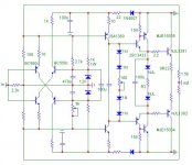
Some times it goes up to 200-300mV at start, but sometimes not, shootin much. I am suspicious of the Zeners when cold or hot because DO-41 glass mini cases. About the Vgs (off) kick of the JFET CCS I have seen no difference in output pair Iq per side. Upper CCS resistor from common base cascode transistor base and Zener node being a trimmer is necessary anyway because the PNP input side has lower Vbe. And it centers OK in general. Could work without comp but with a step network it showed better square wave on rising and trail edge.
I have a solution to the drift...
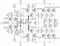
1. You Can use it or not. The 2 input transistor should be feed by an current mirrors feed by a shared currentsource Like cr200..
2. the cr200 Will give an idle current of 2mA +/-10%.. this Will reduce the basiscurrent and remove the heat. The baseresistor for the next stage has to be 5x larger..
This solution is taken from my mirand AMP.
I have a drift starting at 300mV falling to ~50mV. And i Will ADD the circuit above
Can you show it schematically? Thanks.
Nice. You had CCSed the input current feed substituting the current feed resistors. Something that Lazy Cat had talked about as an option early in the thread, pointing out the PSRR benefit mainly. But it proves DC conditions stabilizing also. A few patches and this front end will be a true all rounder probably. 
What happend with the vBE voltage and Hfe as the temperature rises??
First The VBE falls of with ~2mV/K and second the gain rises.
So all extra current that does not go into R12 and R13 goes into the base of Q3 and Q6 and the Collector current goes up... When the collector current goes up the temperature rises more....
As the room temperatur goes up and down so does the the collector current alot!
This leads to an uncontrollable idle current in Q3 and Q6.. You will not be able to make to identical amps as you cannot get transistors with the same HFE and VBE drop....
The 22R emitter resistor is basic control of the current in an BJT.... Just basic.....
No, this is not drift... It is more how stable the idle current is in the VAS stage.
This will influence a bias circuit for the output stage. If it is a simple resistor with a bypass cap for driving mosfet's then you are in trouble. If you have a a VBE multiplier you will see a bias current in the output stage that drift a bit more than desired....
This will influence a bias circuit for the output stage. If it is a simple resistor with a bypass cap for driving mosfet's then you are in trouble. If you have a a VBE multiplier you will see a bias current in the output stage that drift a bit more than desired....
Nice. You had CCSed the input current feed substituting the current feed resistors. Something that Lazy Cat had talked about as an option early in the thread, pointing out the PSRR benefit mainly. But it proves DC conditions stabilizing also. A few patches and this front end will be a true all rounder probably.
Nope, my main intention was exactly the same - feedback bridge DC current injection control. Look to the SSA high performance version and you will see its identical role.
What we can benefit from sonnya's current mirror proposal is that we can symmetrically control both positive and negative injection currents with LM314 current-temp sensor instead of cr500. In that way we can completely eliminate input stage bias thermal dependency.
Last edited:
do you really believe bipolar has a 'sound'? I thought that the topology and operating points and power supply are going to have a bigger impact on the sound than choice of FET verses BJT
Each device has their own characteristics (such as Ciss in a mosfet). This will make them "sound" different. You cannot always put them on the same operating condition. For example, make a class-B amp using hexfet (with highish Ciss), you can design a high current drive, but the sound will never be the same.
Of course topology, operating points and power supply are also important. In fact, all are important. Even MJL versus NJL is important. They have to be "designed" as a whole complete system, including the speaker and the source.
If my (ultimate) speaker has 100dB/m sensitivity for example, I will not look at this type of amp design.
The SSA has it's weaknesses - thermal stability is one of them - in my opinion, and use of zeners (noisy things). And I think it will sound better if it's NOT actually symmetrical - an easy thing to achieve
Do you think 2nd harmonics would be a plus? I'm going to compare with Mooly's amplifier attached where it is asymmetrical. But I have one question before I modified my amp to use the same lateral mosfet and to use negative supply opamp:
The amp attached uses TL071, a JFET input that is wired with negative supply. I have checked the parameters of my opamps, but I couldn't find which feature that allows use of negative supply only. I have some TL061CP which is also JFET-input from the same manufacturer (TI). Do you think I can wire it with negative single supply? Which parameter in the opamp that I should look for to know that the opamp is capable of this negative supply?
Attachments
Nope, my main intention was exactly the same - feedback bridge DC current injection control. Look to the SSA high performance version and you will see its identical role.
Sorry If I did not follow those posts, the PSRR thing I remembered from this early one quoted below:
Only resistor devider for the bases of the cascodes in Le Monstre really can not provide any isolation from power supply ripple or DC variations, so poor PSSR is quite obvious. In my sch +/- 15 V zener filtered DC potential is substantially more adequate solution. If there would be CSS implemented instead of 1 k input pair current supply resistors, PSSR would be comparable to any CF amp.
As I already mention for such low power amps there is not a big problem to invest a little more in the power supply, which can be for this kind of current consumption even regulated to improve PSSR.
Sorry If I did not follow those posts, the PSRR thing I remembered from this early one quoted below:
Yes Salas, it was the PSRR debate but later on the topic was mainly concentrated to bias current thermal dependency and its cancellation. Current mirrors with middle current-thermal sensor is a pro-solution. I think LM134 linear response is adequate to maintain the currents in correct range to sustain stable working point conditions of the input pair.
- Status
- This old topic is closed. If you want to reopen this topic, contact a moderator using the "Report Post" button.
- Home
- Amplifiers
- Solid State
- Simple Symetrical Amplifier