Yes Salas, it was the PSRR debate but later on the topic was mainly concentrated to bias current thermal dependency and its cancellation. Current mirrors with middle current-thermal sensor is a pro-solution. I think LM134 linear response is adequate to maintain the currents in correct range to sustain stable working point conditions of the input pair.
Hi, can you point to a schematic with those in SSA front end? They are substituting the current feed resistors I suppose. Using a trimmer in one for adjustable current set? Any extra components? There is a 10mA max that will not allow much less than 100R emitter to ground at input transistors, yes?
Thank you gentlemen. I think I had this almost correct, then came home last night after a wine tasting and tried to quickly finish up while rearranging for neatness. Hey, at least I didn't try to fly a jetliner. OK, I think I'm there. One question, how important is the low input impedance? My system can handle it, so just curious what we can get away with.
Sheldon
Sheldon
Attachments
Member
Joined 2009
Paid Member
Sheldon, you have drawn the TGM5 version of SSA, more or less 
Trouble with a low input impedance, in my case, is the use of a fairly high resistance passive (potentiometer) volume control before it is more challenging and of course, any caps you put in front need to be much larger or you lose bass response. As with TGM5 I suggest that you want to allow a provision for compensation caps on the CFP drivers as they like to oscillate if provoked (e.g at start up).
Trouble with a low input impedance, in my case, is the use of a fairly high resistance passive (potentiometer) volume control before it is more challenging and of course, any caps you put in front need to be much larger or you lose bass response. As with TGM5 I suggest that you want to allow a provision for compensation caps on the CFP drivers as they like to oscillate if provoked (e.g at start up).
Last edited:
Apassgear,
No disrespect intended, I always get a little concerned by power nuts. It is always a good measure to make the SSA as it was intended, familiarize yourself with it quirks, shortfalls and advantages, and most importantly get a feel for its sound whether it lives up to your expectation before pouring a bucket of transistors into it.
It is relatively easy to expand when you are satisfied that it is the amplifier that you want to live with.
Hi Nico,
I think this is the first time we "meet" at a thread, thanks for your advice and of course you are right. Even though I have built an Aleph 4 does not make me a power nut, what I'm after (as most of us) is the repro of the full audio BW at low to medium volume that suits one's speakers and of course with attributes such as the ones SSA has. From the amps I have built the FW F5 is near to what I need. Now that I'm writing this I realize that all the built amps have been with FET at the output, except for the tubed ones.
Maybe is time for me to try something different such as Lazy Cat's full BJT circuit shown on post 1319.
Cheers, Tony
Last edited:
Sheldon, you have drawn the TGM5 version of SSA, more or less
Indeed. I'm debating whether to build TC's simple thermaltrak version, or this one. I have the various devices left over from my FC 100 builds (ironically, the only active devices I don't already have in the bin are the common as dirt BC560).
Trouble with a low input impedance, in my case, is the use of a fairly high resistance passive (potentiometer) volume control before it is more challenging and of course, any caps you put in front need to be much larger or you lose bass response.
Didn't you trace some thermal stability problems to higher input impedance? I'd use this amp for the mid-highs in a multiamped system, driven by a DEQX, so low impedance is not an immediate issue. But for possible future application, it'd be nice to know the possibilities.
As with TGM5 I suggest that you want to allow a provision for compensation caps on the CFP drivers as they like to oscillate if provoked (e.g at start up).
No problem, as build will be on perf board.
Sheldon
Last edited:
Member
Joined 2009
Paid Member
Indeed. I'm debating whether to build TC's simple thermaltrak version, or this one. I have the various devices left over from my FC 100 builds (ironically, the only active devices I don't already have in the bin are the common as dirt BC560).
I would suggest you use the Thermaltrak's that you have - good use of good parts. A Thermaltrak TGM5 !
Didn't you trace some thermal stability problems to higher input impedance? I'd use this amp for the mid-highs in a multiamped system, driven by a DEQX, so low impedance is not an immediate issue. But for possible future application, it'd be nice to know the possibilities.
Yes, I did, but in simulations only - haven't had a chance to build it yet. I think there are diminishing returns below 10k or so because the low impedance helps only with the offset due to mismatch of input devices - it doesn't help if they aren't well thermally coupled and it does nothing to help imbalance caused by temperature differences in the VAS devices. The latter is something I'm not too worried about but it's another factor.
I would suggest you use the Thermaltrak's that you have - good use of good parts. A Thermaltrak TGM5 !
That's a given. Decision is whether to use simple version or CFP version.
Sheldon
Member
Joined 2009
Paid Member
I like the CFP because I believe the Triple better isolates the VAS from the non-linear impedance of the output devices. Everyone has their own preferences I guess - Hugh prefers a Triple based on a Diamond Buffer, OStripper prefers a Triple based on cascaded EFs.
The CFP hates Class B, so in the driver position it must be kept in Class A with sufficient current flow. I like that it doesn't rob me of any voltage headroom compared with a Triple based on Cascaded EFs and that it doesn't need current sources like a Triple based on Diamond buffer (I don't like current sources or current mirrors).
The CFP hates Class B, so in the driver position it must be kept in Class A with sufficient current flow. I like that it doesn't rob me of any voltage headroom compared with a Triple based on Cascaded EFs and that it doesn't need current sources like a Triple based on Diamond buffer (I don't like current sources or current mirrors).
Hi,
I see the discussion is going in many different directions since last time when I checked, but I hope some of you may find my last findings useful.
In my previous post #937
http://www.diyaudio.com/forums/solid-state/193923-simple-symetrical-amplifier-94.html#post2726951 I had various problems with Lazy Cat's SSA. I know most of you are trying more complex schematics derived from the simple one, but I am too stubborn or just silly, and wanted to make the original simple one to pass my usual amplifier tests. Finally, I had to discard the use of vertical MOSFETS and BJTs, because of their high temperature drift. I can assure you that I've spent hundreds of hours (I'm not exaggerating) and tried many output configurations. None of them had stable quiescent current and no modification or change in the schematic values gave me reliable results.
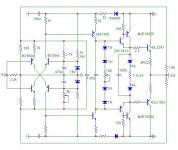
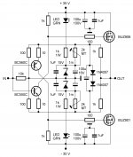
So, I bought laterals BUZ906P and BUZ901P. With them I could go back to the original schematic with just a trimmer for current adjustment. These transistors have their own limitations, one of them is that they are not very well matched N to P channel at low currents. Another one is low gain (transconductance). Third one is that they work better with higher idle current (150mA is the reasonable minimum).
After many tests I attach here my version of the schematic. I used the drawing of the forum member juma as a template.
With the new values I solved some additional problems:
1. Circuit gain was not constant with the original values in the feedback. It was dependent on the output load and the output amplitude. The amp behaved like one with high output impedance, but mostly due to circuit gain change. I noticed variations from gain of 10.5 to 7. Lower feedback resistors values solved that.
2. I tried to balance the laterals for minimum distortion. See the change in their gates. Of course its just in the ballpark. It's impossible to match for all Vgs/current values.
3. My SSA version has 4MHz oscillation that tends to show itself with some speakers and cables. I added capacitors for stability. Values depend on how brave are you and how much risk you would accept. I am not brave, but you can even run it without capacitors.
4. In the original SSA, with one channel loaded at half power, I noticed that the other channel changed its otput DC component from 10mV to, say, 200mV. After investigation I found it was due to insufficient current in the Zeners. When the supply drops several volts, the current in zener diodes goes close to the "knee" value and the regulation is lost. So, I increased significantly the Zener diodes current. Have in mind that much of it is robbed trough R12/R13 and R11/R14. As Lazy Cat suggests, regulated supplies are good option for this amp.
5. With the new values the voltage in the nodes R12-R13-R7 (resp. R11-R14-R10) was insufficient to put into conduction Q5 and Q6, so I had no choice but to increase the Zener voltage with 18V diodes.
6. Due to the higher currents you'll need 0.5W or 1W resistors as marked on the schematic.
7. The laterals like more current. If you run them at less than 150mA, there is prevailing 3rd harmonic. It will completely disappear at higher idle current. The idle current is stable about 10 minutes after turn-in. DC component is stable too. It will change from about +/- 10mV to about 100mV at half power. If you adjust the laterals for more idle current (say 250mA), the DC component will not change to more than 30mV at half power.
8. I like capacitor at the input. IMO, it solves more problems than it creates.
That's all so far. The amp sound is very good, but I'll give it more listening once I build decent boards and put it in an enclosure. The original version sounds kind of too warm and one-note in the bass to my ears. My definition for good sound is detail and definition, but not on the "clinical" side. The type of 300B single-ended comes to mind. I think this circuit has the potential to be close.
If you are interested, Nelson Passes' F5 article (manual) and his Super Symmetry article are very interesting reading.
Regards
I see the discussion is going in many different directions since last time when I checked, but I hope some of you may find my last findings useful.
In my previous post #937
http://www.diyaudio.com/forums/solid-state/193923-simple-symetrical-amplifier-94.html#post2726951 I had various problems with Lazy Cat's SSA. I know most of you are trying more complex schematics derived from the simple one, but I am too stubborn or just silly, and wanted to make the original simple one to pass my usual amplifier tests. Finally, I had to discard the use of vertical MOSFETS and BJTs, because of their high temperature drift. I can assure you that I've spent hundreds of hours (I'm not exaggerating) and tried many output configurations. None of them had stable quiescent current and no modification or change in the schematic values gave me reliable results.
So, I bought laterals BUZ906P and BUZ901P. With them I could go back to the original schematic with just a trimmer for current adjustment. These transistors have their own limitations, one of them is that they are not very well matched N to P channel at low currents. Another one is low gain (transconductance). Third one is that they work better with higher idle current (150mA is the reasonable minimum).
After many tests I attach here my version of the schematic. I used the drawing of the forum member juma as a template.
With the new values I solved some additional problems:
1. Circuit gain was not constant with the original values in the feedback. It was dependent on the output load and the output amplitude. The amp behaved like one with high output impedance, but mostly due to circuit gain change. I noticed variations from gain of 10.5 to 7. Lower feedback resistors values solved that.
2. I tried to balance the laterals for minimum distortion. See the change in their gates. Of course its just in the ballpark. It's impossible to match for all Vgs/current values.
3. My SSA version has 4MHz oscillation that tends to show itself with some speakers and cables. I added capacitors for stability. Values depend on how brave are you and how much risk you would accept. I am not brave, but you can even run it without capacitors.
4. In the original SSA, with one channel loaded at half power, I noticed that the other channel changed its otput DC component from 10mV to, say, 200mV. After investigation I found it was due to insufficient current in the Zeners. When the supply drops several volts, the current in zener diodes goes close to the "knee" value and the regulation is lost. So, I increased significantly the Zener diodes current. Have in mind that much of it is robbed trough R12/R13 and R11/R14. As Lazy Cat suggests, regulated supplies are good option for this amp.
5. With the new values the voltage in the nodes R12-R13-R7 (resp. R11-R14-R10) was insufficient to put into conduction Q5 and Q6, so I had no choice but to increase the Zener voltage with 18V diodes.
6. Due to the higher currents you'll need 0.5W or 1W resistors as marked on the schematic.
7. The laterals like more current. If you run them at less than 150mA, there is prevailing 3rd harmonic. It will completely disappear at higher idle current. The idle current is stable about 10 minutes after turn-in. DC component is stable too. It will change from about +/- 10mV to about 100mV at half power. If you adjust the laterals for more idle current (say 250mA), the DC component will not change to more than 30mV at half power.
8. I like capacitor at the input. IMO, it solves more problems than it creates.
That's all so far. The amp sound is very good, but I'll give it more listening once I build decent boards and put it in an enclosure. The original version sounds kind of too warm and one-note in the bass to my ears. My definition for good sound is detail and definition, but not on the "clinical" side. The type of 300B single-ended comes to mind. I think this circuit has the potential to be close.
If you are interested, Nelson Passes' F5 article (manual) and his Super Symmetry article are very interesting reading.
Regards
Attachments
Last edited:
That's all so far. The amp sound is very good, but I'll give it more listening once I build decent boards and put it in an enclosure. The original version sounds kind of too warm and one-note in the bass to my ears. My definition for good sound is detail and definition, but not on the "clinical" side. The type of 300B single-ended comes to mind. I think this circuit has the potential to be close.
If you are interested, Nelson Passes' F5 article (manual) and his Super Symmetry article are very interesting reading.
Regards
Ruwe great job on a SSA Basic version you did, congratulations. My basic version differs in a way that I always used BIGBT's as outputs, so having lower output impedance and probably less issues than in your's really basic version. It can't be even simpler than this as Elvee suggested to omit cascodes without significant change, than you've had only four transistors in your case. Well I don't know if that would work with the same bandwidth and same stability.
But what Elvee found out from his simulations is lowering the overal distortions from 0,3% to 0,07% if there are no 10 ohm emitter resistors present in the input stage. So my suggestion would be to check the optimum values of these two resistors to find the best correlation between harmonic distortion profile and best sound of this basic version. If you like you can even check what happen if you omit casodes. Of course you can leave it like it is now, it is good sounding simple amplifier anyway.
Thanks Ruwe for your contribution to this thread and DIY audio community, your info is of a great value to all of us, regards Andrej
Last edited:
They need thermal compensation, for sure.I had to discard the use of vertical MOSFETS and BJTs, because of their high temperature drift.
Let me think you have a poor PSU ?1. Circuit gain was not constant with the original values in the feedback. It was dependent on the output load and the output amplitude. ...
4. In the original SSA, with one channel loaded at half power, I noticed that the other channel changed its otput DC component from 10mV to, say, 200mV. ...
btw: feedback resistances needs to be at least 3W.
I believe the issue can be better addressed those ways:My SSA version has 4MHz oscillation that tends to show itself with some speakers and cables. ... I added capacitors for stability.
- Accurate shield of Amp & PSU.
- Is your R5/R6 soldered right at the gates ?
- Did-you use some Selfic resistances somewhere ?
- Avoid Parasitic caps in the Feedback ends (Did your response curve show a peak between 4 & 10 Mhz ?)
- Playing with some Boucherot cell (Snubber) ?
- Following your needs, and if you drive very capacitive loads, i would consider a self+R in // in serial of the output (Tank ? = circuit 'bouchon' in French).
It is a pity to reduce too much the bandwidth. I would try to keep-it flat up to 2Mhz. Here too the supply impedance at high frequency and correct decoupling with film caps on the PCB can have a huge influence.
The first thing would be to try to get your amp clean without C in CR. Then, tune one //C in the feedback loop just enough to get a flat response curve at HF if needed. Then a low pass filter in the input to kill any overshoot on square waves. Just at the limit for each step.
If you understand French (or can use some Gougeule translation), that is the ways i had addressed those issues on my SSA amp:
www.esperado.fr - Le crescendo revisité
and the power supply:
www.esperado.fr - Alimentation Crescendo
My two cents.
Last edited:
... and Ruwe one more thing regarding stability issues and consequently the amp's bandwidth (omiting 220pF caps), bases of cascode transistors needs 1uF to GND for HF stability, ELCO itself doesn't provide low Z in MHz region. Using 1uF decoupling in all DC points helps stability in this amp more than you can think of. Also use 1000uF instead 220uF in parallel with zeners.
Hi Christophe, thanks for your contribution too.
Hi Christophe, thanks for your contribution too.
Ruwe had very strong DC problems initially and he worked a lot to make it viable. Nice. To have less THD it would take to add drivers of some kind is one good plan I think. Omitting 10 Ohm will help THD but let Iq wander more with temp? Andrej, until getting some LM334, what do you think about JFETs as current feeds? I got some that take some time to reach top IDSS with temperature, if I blow over them they lose some. Benefit is they are extremely quiet, when LM334 datasheet says it will add 12dB of noise. But can such JFETs help our input transistors Tc thing?
Hi Salas
Drivers and source follower output mos-fets would certainly lower the THD, but in a simplest version like this is, optimization (not complete absence) of the Re's values can bring some improvement - balance between THD & sound quality. Definitely worth to try in this phase of the construction Ruwe is now.
Current feeds to the bridge with j-fets is a good idea because of their negative tempco, similar temperature dependency like input BJT's, only reverse. It would be a simple one j-fet solution per 15 V rail, of course adjustable to optimum current value with gate-source resistors. BF245B seems to be appropriate type, 6-15 mA drain current, HF, low noise, ... If this solution would prove to be adequate, than you can simply omit j-fet from your VAS stage.
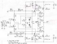
P.S. To explain a bit, this one runs half current on input transistors than before to keep them cooler and hopefully tamer, hence the 1K cascode loads that were 470R before. The drivers are BD140/139 still, just the spice models are from NXP same die surface mounts. Output bias target is still around 175mA, that spice predicted very well before I must say. With the current feeds there is 5dB more OLG predicted also.
SSA Basic MOS-FET
SSA Basic MOS-FET version with J-FET current sources to provide supply current into SSA feedback bridge, serves to compensate collector current thermal drift of the input pair and consequently the bias of the whole amplifier.
This version was inspired by Salas, based on Nico's mos-fet SSA amplifier from early of this thread.
Attachments
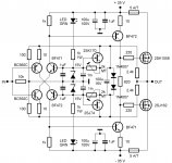
SSA Basic Easy
SSA Basic Easy simplest of them all, only four BJT's, inspired by Ruwe, based on Elvee's suggestion.
I know most of you are trying more complex schematics derived from the simple one, but I am too stubborn or just silly, and wanted to make the original simple one to pass my usual amplifier tests.
SSA Basic Easy simplest of them all, only four BJT's, inspired by Ruwe, based on Elvee's suggestion.
Attachments
- Status
- This old topic is closed. If you want to reopen this topic, contact a moderator using the "Report Post" button.
- Home
- Amplifiers
- Solid State
- Simple Symetrical Amplifier