I saw very little additional value in regulating the supply to the zener diodes as the diodes are themselves a regulator - it's like regulating the supply to a regulator - diminishing returns. If you were to regulate the supply you may as well consider getting rid of the zener diodes since they add their own noise. The fdbk node voltage is set by the current flowing through the relevant resistors - and this current flow depends on the voltage from the zener's. It does benefit from being as quiet as possible and a zener is a fairly crude shunt regulator - but it is simple and this alone can be a real benefit. The noise generated by the zener can be shunted away by the bypass capacitor and here you really do want to use a good cap, low ESR and large value.
Based on these noise measurements, I doubt that a cap would provide much benefit in that regard: http://www.diyaudio.com/forums/part...surements-leds-zener-diodes-7.html#post417008 Can't get much quieter than that.
A cap might contribute more noise that it removes. The real issue (if there is an audible one) would be the impedance of the zener. The values I see are around 10-30R. That dictates the cap value (if one is actually required).
I'm not sure that crosstalk is much of an issue either. Maybe it depends on whether or not it's in or out of phase, but records sound fine and they have 30dB separation under the very best of circumstances.
Sheldon
try OsCon's you might be surprised
Thanks, I will dig my parts to find them!! (how can I forget about them). BTW, do you know where I can make use of tantalum caps? I couldn't find a good application for them

Member
Joined 2009
Paid Member
A cap might contribute more noise that it removes.
From what I've read, larger value caps (electrolytic) mean less a.c. voltage developed across them which produces less distortion. Bigger is better, providing the cap is high quality to begin with. I recommend the polymer caps.
OsCon's are a sort of polymer caps... maybe tantalums might work too...never tried them
Naaah... tantalum ime are always terrible. Even at HF they are not the best. I just checked my computer/PABX/telecom devices to find out why and what for they are used there. Mostly they are used to bypass power supply pins of opamp or logic IC. I think it is because for some applications higher capacitance (in the order of 6.8uF and above) is required to bypass these pins (for small capacitance bypass, MKM and others are used instead). Then why not ordinary elcos? May be because of durability issue. One of my Macintosh computer uses the axial blue Nichicon, which is one of the BEST cap that I know, and no tantalum... I guess tantalum is only for practicality.
BTW, I hope somebody will come up with a perfect implementation of a SSA LATFET, complete with the separate regulation for the front end. I have been waiting for a mosfet amp that has the magic of my AKSA-clone. From the simplicity of the design, from Nico's report (and Esperado's report for the SSA Crescendo), and from my experience with the Le Monstre, it could be this amp.
Member
Joined 2009
Paid Member
Naaah... tantalum ime are always terrible.
Tantamum caps aren't all bad - see attached for some notes I found on the internet >Tantalum Capacitors About - Engineers Edge
I have been waiting for a mosfet amp that has the magic of my AKSA-clone.
I think the SSA will sound different from the AKSA-clone, being symmetric for starters. Why not simply try MOSFETs as an output in an AKSA-clone circuit ?
I agree with you, the SSA has garnered a lot of praise from people whom we trust and should be worth the effort of building one.
Attachments
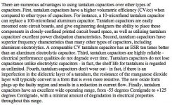
Tantamum caps aren't all bad - see attached for some notes I found on the internet.
Sure they are good for practical purposes, but for critical sound system, they are bad
I think the SSA will sound different from the AKSA-clone, being symmetric for starters. Why not simply try MOSFETs as an output in an AKSA-clone circuit ?
Sure they will sound different. If not, why should I need a mosfet version
It's interesting if the AKSA circuit can be used for (lateral) mosfet output with optimal result. They are different devices, most probably need different treatment.What I need is the TRANSPARENCY of the AKSA-clone. First is the simplicity (may be I don't need the front end regulator after all), second is the distortion pattern, third is the speed, fourth is the noise figure. The last one is about layout and grounding (i.e. careful implementation).
I agree with you, the SSA has garnered a lot of praise from people whom we trust and should be worth the effort of building one.
The circuit itself is very simple, using very high current gain devices (TO-92) such as A970/2N5401 which ensures speed thus transparency. If it works, it must be very good. Next step is to tweak the circuit to get the "sweetest spot".
Unfortunately, you (and the other very "active" members) choose the BJT version. Hopefully Salas will come up with a superior circuit, tho I doubt it, because his motivation imo is different
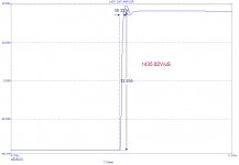
What is your definition of speed? You can tweak each component value in the amp to theoretically have slew rates of over 1000V/us, is this what you mean by speed? Problem is you start running into serious stability problems and your PCB layout has to follow the rules of a linear RF layout. It could take weeks or even months of experimenting and placing arbitrary caps between tracks to achieve this, where the black art of RF lurks - would it make much difference in the sound character between this and what we already have?
Attachments
Hopefully Salas will come up with a superior circuit, tho I doubt it, because his motivation imo is different
What do you infer?
Has someone checked the output offset stability in respect
of temperature variation ?..
So far, the sims say that the shift is about 100mV/25° , that is 4mV/°C.
A servo can be necessary.
I wonder too..
Could we get a list of drift from build amplifiers? Also the difference of shorted and non shorted input with the size of the input resistor!?
Jay, The AKSA is not particularly transparent. Subjectively it may seem so, but there is considerable second harmonic.
Yes, I have been expecting this comment, as I was not so sure what "transparent" should mean to everyone
The sweet tubey sound is the second harmonic right? What I mean with transparent is the perception as if the singer is there (along with the emotion that always draw my attention to the music). No bipolar amp that I have heard can beat my tube amp (in the past) in term of this. But my AKSA clone strangely can beat my class-A amp in this aspect, that's why I keep it, even tho bipolar sound is not my cup of tea.
But I have had similar experience with hexfet amp so I think that this is possible with any kind of output transistor. Tho I doubt a complex amp can do it easily, especially symmetrical amp. But man, the SSA is simple and perfect physically. I really hope that with 47Vdc I can get more power with single pair of output latfet and single TO-92 driver.
I personally think that this off-set and drift is audiophile hype. Show me an N and P junction transistor that has identical characteristics over a wide temperature range. I would argue that gluing two non identical tansistors together worsens this rather than improves it. Unless two transistors are on the same substrate and physically matched by the manufacturing process, forget it.
So what difference does it make to the sound if the positive half cycle swings a few mV higher, the output remains symmetrical between positive and negative swing anyway. Whether the speaker cone has a electrical rest position which is slightly different from the mechanical rest position still make no difference the compression and rarefaction of the air is still exactly the same. It remains an audiophile mystery.
So what difference does it make to the sound if the positive half cycle swings a few mV higher, the output remains symmetrical between positive and negative swing anyway. Whether the speaker cone has a electrical rest position which is slightly different from the mechanical rest position still make no difference the compression and rarefaction of the air is still exactly the same. It remains an audiophile mystery.
What do you infer?
Well, so far only you and Nico take the challenge to experiment with the latfet version. I guess you won't be as motivated as Bigun and others to get the best out of your amplifier building (and share them to public). And Nico is a professional who tends to keep his work as his property.
As for Bigun, we can at least see 5 versions of TGM so far. But that's all BJT amp, not my favourite output device. Lazycat's IGBT output stage is acceptable soundwise but IRF610/9610 is not good enough imo (Yes I have a better device but forget where they are).
I'm interested in Wahab's triplets, but as you know, he just threw a simulated circuit and then stopped there.
If my lateral is as cheap as my bipolar, may be I don't need to rely so heavily on the experts to build my amp
So what difference does it make to the sound if the positive half cycle swings a few mV higher, the output remains symmetrical between positive and negative swing anyway. Whether the speaker cone has a electrical rest position which is slightly different from the mechanical rest position still make no difference the compression and rarefaction of the air is still exactly the same. It remains an audiophile mystery.
I challenged anyone over on the fetzilla thread to give one logical reason why 100mV of offset would create any kind of a problem. One person said he thought it gave less detail - apart from that there was not one reason anyone could come up with. Personally, having been living with offset between + / - 70mV these last 6 months I see absolutely no problem and also no loss of detail and I noticed recently that Peter Daniel's DC linked chip amps regularly go up to about 70mV.
Do I expect people to stop fussing about it ? ? . . . well . . . no, it seems that the idea of DC offset is unpopular.
Unless of course you want to connect an o/p transformer for impedance matching - but in a DIY community it might be better to built the amp right in the first place
Well, so far only you and Nico take the challenge to experiment with the latfet version. I guess you won't be as motivated as Bigun and others to get the best out of your amplifier building (and share them to public).
Each step of my experiment has been publicized here, I don't see how you came to that reasoning. In a nutshell I am trying for a medium power BJT-Latfet Sziklai following the work of LazyCat plus Nico additions, trying for best safety and stability. Differences are I go for high gain, inevitably less feedback, around 12dB left for it in the Tian method LTSpice analysis with my now drivers. Also controlled the bandwidth to 1MHZ -3dB (measured) for good square waves up to 50kHz without input and output filtering yet (can be needed on real speakers). My goals are never to achieve ''best'' in general but rather ''adequate''. I had even checked 300MHZ Ft Sanyo video transistors for drivers but the amp went too speedy for keeping oscillation trouble at bay. If it will safely and stably outperform the F5 standard in the long run (a rather comparable concept but high bias) in my system (speakers having a 4ish Ohm orchestra power region Z curve) I will be content.
- Status
- This old topic is closed. If you want to reopen this topic, contact a moderator using the "Report Post" button.
- Home
- Amplifiers
- Solid State
- Simple Symetrical Amplifier