Nice amp - a few tips ...
I'm glad you gave credit to the great Dr. Self. His topology can create great sound.
I read the WHOLE thread...
I have recently run into 2 of your builder's problems , #1. sticking #2. oscillation
either after sticking or with very high gain devices.
#1 - you have solved that") just a reverse diode across the miller (called a "baker clamp")
just a reverse diode across the miller (called a "baker clamp")
Choose your diode carefully , one with high reverse leakage can increase distortion considerably.
#2.- The dreaded oscillation - you chose wisely.. 22R for the MJE-xx and 2.2R for the
outputs are perfect for these devices.
Increasing the value of the stoppers is at best just a "band-aid" and won't solve
the problem.
You must learn the ways of "Gain Margin and Phase Margin - measures of stability"
http://www.hpc.msstate.edu/mpl/education/classes/ee8223/pp116-123.pdf
With one builders (still4given) oscillation , I could easily recreate it after "sticking" ...
the simulator recreated his problem EXACTLY as his scope showed.
Another builder used ultra high gain input transistors and I also recreated an
oscillating amp using (models of) his transistors.
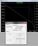
(Attachment 1) is a stable amp , even after sticking just a very short burst
as the VAS transister "recovers". Notice it has -90 degrees phase.
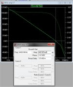
(attachment 2) is the amp that really did oscillate in the "REAL world" .
In the second attachment the phase is -127 degrees - bad... 180-127 = 53 degrees "phase margin" .
78 degrees or more is where an amp becomes "rock solid" stable.
I increased that margin by increasing the emitter resistors on the input pair.
You can also increase this margin with a higher value VAS emitter resister or
increasing the current mirror's emitter resistor values.
Have you run a loop gain analysis of this amp ??
PS - These are not criticisms of your amp's design , it's design is standard
"blameless" and can be optimized. I want it (your amp) and it builders to
be .
OS
I'm glad you gave credit to the great Dr. Self. His topology can create great sound.
I read the WHOLE thread...
I have recently run into 2 of your builder's problems , #1. sticking #2. oscillation
either after sticking or with very high gain devices.
#1 - you have solved that
just a reverse diode across the miller (called a "baker clamp") Choose your diode carefully , one with high reverse leakage can increase distortion considerably.
#2.- The dreaded oscillation - you chose wisely.. 22R for the MJE-xx and 2.2R for the
outputs are perfect for these devices.
Increasing the value of the stoppers is at best just a "band-aid" and won't solve
the problem.
You must learn the ways of "Gain Margin and Phase Margin - measures of stability"
http://www.hpc.msstate.edu/mpl/education/classes/ee8223/pp116-123.pdf
With one builders (still4given) oscillation , I could easily recreate it after "sticking" ...
the simulator recreated his problem EXACTLY as his scope showed.
Another builder used ultra high gain input transistors and I also recreated an
oscillating amp using (models of) his transistors.
(Attachment 1) is a stable amp , even after sticking just a very short burst
as the VAS transister "recovers". Notice it has -90 degrees phase.
(attachment 2) is the amp that really did oscillate in the "REAL world" .
In the second attachment the phase is -127 degrees - bad... 180-127 = 53 degrees "phase margin" .
78 degrees or more is where an amp becomes "rock solid" stable.
I increased that margin by increasing the emitter resistors on the input pair.
You can also increase this margin with a higher value VAS emitter resister or
increasing the current mirror's emitter resistor values.
Have you run a loop gain analysis of this amp ??
PS - These are not criticisms of your amp's design , it's design is standard
"blameless" and can be optimized. I want it (your amp) and it builders to
be
.OS
Attachments
Last edited:
Despite nice the intention to cooperate
I would like to sign to forum folks that Andrew T and also Ostripper are not Dx consultants, nor representatives, so, their opinions are their opinions.
This amplifier is an evolution of so many other models, not anymore a copy from Doctor Self Blameless.... was inspired into the Blameless, but you can see it has some differences.
Friends will call these differences as clever evolution.... less friends will call this flaws.
Making some examination from the past i would be afraid to say these gentlemen, studying historical moments of this forum, do not seem to be all that friendly.
I do not use to read them, as often i could find not nice gestures from them.... they are in the ignore list, they post and i do not read them.... well, some of them have their own amplifier to worry about... some are modified, other are genuine copies.
Several group buys already runned, several foruns offered as group buy wide world.. something alike 280 guys assembled using the pcboards we have offered, others built etching the unit by themselves.... 3 guys reported troubles when clipping ....you see, this is a very little ammount of troubles people faced if you calculate the percent.... and many times is due to their part selection or failures when building.
Mr Smartx21, a very competent builder, a high end audiophile from Brazil, is also not a close friend...we had our troubles in the past.... when have criticisms, they use to come in group to "help".... all ignored land in group to help
You all know this kind of helping hand when the someone report problems.
Our forum has more than 200 thousand members...i have some members in my ignore list..try to imagine why?... well...it is a long story.... all them skilled, competent and nice guys...but not my friends....this was proved many times before.
regards,
Carlos
Attachments

Last edited:

Thanks dear Terry, much appreciated your comprehension
You see what happens when someone report problems.
I will reach 10 long years in this forum...i know forum people very well..their behavior..what they want..what they need and so on.
Much appreciated Terry.
regards,
Carlos
You see what happens when someone report problems.
I will reach 10 long years in this forum...i know forum people very well..their behavior..what they want..what they need and so on.
Much appreciated Terry.
regards,
Carlos
Hi Guys,
I have finished building the boards I received in the newest group buy. I have a hum problem that we have been trying to resolve in the newly created builders thread but that has brought up some questions and since some or you who have built these may be following this thread and not that one I would like to bring your attention to it so that maybe you could chime in. The issue is that I get a bad hum as soon as I connect both inputs to a source. I tried several different sources and all do the same thing. so then I tested it with shorted inputs and as soon as I short the grounds of the input together I get the hum. A fellow member here, while trying to help noticed this.
That in is reply to the schematic and boards shown in this post.
After looking over the schematic I see that on these boards the grounds for C15a,b and C11a,b are all tied to the same trace as the input ground. Could this be causing the ground loop? Have any of you experienced the same thing I am?
Thanks, Terry
I have finished building the boards I received in the newest group buy. I have a hum problem that we have been trying to resolve in the newly created builders thread but that has brought up some questions and since some or you who have built these may be following this thread and not that one I would like to bring your attention to it so that maybe you could chime in. The issue is that I get a bad hum as soon as I connect both inputs to a source. I tried several different sources and all do the same thing. so then I tested it with shorted inputs and as soon as I short the grounds of the input together I get the hum. A fellow member here, while trying to help noticed this.
"If posted pictures (schematic and PCB) are valid, than here are following faults:
To input signal ground should be connected only R01, C04, C06, C07 and one end of R31, 10R. To this point also should be connected input RCA ground , but input conector must be isolated from chasis. And nothing more!
To input signal ground can not be connected C15a, C15b,C11b C11a , it is AC short circuit from suplly voltage on signal ground (AC short circuit for 10R), via PSU main capacitors it is AC shorted to power GND! Also reconnect C01, R17, R08b to power ground.
In current state R31, 10R, have no function.."
That in is reply to the schematic and boards shown in this post.
After looking over the schematic I see that on these boards the grounds for C15a,b and C11a,b are all tied to the same trace as the input ground. Could this be causing the ground loop? Have any of you experienced the same thing I am?
Thanks, Terry
Yes, but so is C11a,b & C15a,b Are those supposed to share the "lifted ground"?
Here is what I found and did. I reinstalled the jumper @ R30 per Carlos' suggestion. Then I installed 10R 1W resistors at the ground post at the RCA connectors. That completely solved the hum induced when connection both inputs from the source. I had a small hum beside that on both channels. That turned out to be from my PSU. seems leaving big electro caps in a drawer for 7 years is a no-no. I did reform them but there is still about 34mVAC ripple on them and that was audible. Looks like I'll have to order some when I have the money. I hooked it up to my DX PSU and a 40-0-40vac transformer and it is dead quiet now. Thanks for the help everyone.
Blessings, Terry
Yes, but so is C11a,b & C15a,b Are those supposed to share the "lifted ground"?
Here is what I found and did. I reinstalled the jumper @ R30 per Carlos' suggestion. Then I installed 10R 1W resistors at the ground post at the RCA connectors. That completely solved the hum induced when connection both inputs from the source. I had a small hum beside that on both channels. That turned out to be from my PSU. seems leaving big electro caps in a drawer for 7 years is a no-no. I did reform them but there is still about 34mVAC ripple on them and that was audible. Looks like I'll have to order some when I have the money. I hooked it up to my DX PSU and a 40-0-40vac transformer and it is dead quiet now. Thanks for the help everyone.
Blessings, Terry
Terry,
Place this info in the 2013 DX build too .....
Edit: See you have already done so ..........
Yes, but so is C11a,b & C15a,b Are those supposed to share the "lifted ground"?
Terry you raise a good point here. My understanding is that the rail bypass capacitors should have their own return to the star ground point. Otherwise they tend to inject rail noise into the signal ground.
I'm glad you solved your problem which sounds like a typical ground loop through the common channel ground of the input source. It might not be at all related to the bypass ground issue you raised. The rail bypass issue remains a concern and could still contribute noise to the output. It could probably be addressed by a simple board mod. I might consider that next time I have the lid off.
Still4,
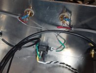
I like the screened two core for the signal input.
I also like the screen going to chassis where it belongs.
Try taking the screen with a VERY short pair of pigtails to the Chassis right next to each input socket. The screen needs to "short" or Shunt the VHF to Chassis to be very effective. Long pigtails offer a high impedance to the VHF interference.
While you do that, try to minimise the length of unscreened wires going to the rear of the socket.
I agree with Bonfis:
the decoupling is the Power Ground and needs to be kept separate from the Signal Ground. That is where R31 comes into play, maintaining that separation.
Yes, but so is C11a,b & C15a,b Are those supposed to share the "lifted ground"?
Here is what I found and did. I reinstalled the jumper @ R30 per Carlos' suggestion. Then I installed 10R 1W resistors at the ground post at the RCA connectors. That completely solved the hum induced when connection both inputs from the source. I had a small hum beside that on both channels. That turned out to be from my PSU. seems leaving big electro caps in a drawer for 7 years is a no-no. I did reform them but there is still about 34mVAC ripple on them and that was audible. Looks like I'll have to order some when I have the money. I hooked it up to my DX PSU and a 40-0-40vac transformer and it is dead quiet now. Thanks for the help everyone.
Blessings, Terry
Terry-
I'm wondering if that leftover hum is from the shared ground situation and not solely due to your 34 mv supply ripple. That amount of ripple doesn't seem at all excessive to me and should be handled by the amps PS rail rejection factor. In looking again at the board it's clear that C11 and C15 share the input ground directly as you said and R30 (or 31) does not isolate them as it should. To fix it you would need to break the C11 & 15 ground traces before they join the signal ground and solder jumpers from there to the nearby main filter cap grounds. That would leave the input ground connected only to the input and FB circuits.
Since my amp also has a slight hum in both channels I'm very tempted to give this a try. Will have to wait though until I get other projects off the bench.
Steve
2n5551 (collector/1k) driving the VAS should also be direct to star (not to the lifted ground).
With a large signal (or VAS saturation) you might create another smaller
feedback loop between VAS-LTP .
I know I am ignored , but this is true.
Silence is "golden", ooops ..
OS
With a large signal (or VAS saturation) you might create another smaller
feedback loop between VAS-LTP
.I know I am ignored , but this is true.
Silence is "golden", ooops
..OS
Last edited:
Hi Guys,
Thanks to each of you for helping with this. I am gaining in understanding all the time.
Bonfis,
I found the cause of the remaining hum. I hooked up my DX PSU to the amp and found I still had a slight hum. Then I noticed that the power cord was still plugged into the back of the case. I unplugged it and the hum went away. This told me that the earth ground was contributing to the hum. I had the center tap plate bolted to the bottom of the case. So, I drilled out the mounting hole and insulated the bolt from the plate and moved the center tap to the end of the plate and the hum disappeared. The amp is dead quiet now.
As for the shared lifted ground, my thinking was to make the "lifting" point at the RCA jacks by inserting the 10R 1W resistors there and just installed a jumper at R30(31). That way C11 & 15 are no longer lifted. They just go directly to ground via the jumper. Maybe that is wrong thinking but it worked.
Andrew,
Yes, I plan to tidy up the shielded cable. That was just a quick trial to see if it would work.
OS, I never ignore you and welcome your insight. You are good at explaining things and I have learned a lot from reading your posts.
Blessings, Terry
I meant (ignore /DX) , not you.
I always tried to help carlos.
He said current sourced amps were sonically inferior.
(then he loves them (blame,the MK3)
Then the ground lift was adopted.
But the science of separating grounds... the "dirty" from "clean"
was lost in the wash.
OS
I always tried to help carlos.
He said current sourced amps were sonically inferior.
(then he loves them
(blame,the MK3)Then the ground lift was adopted.
But the science of separating grounds... the "dirty" from "clean"
was lost in the wash.
OS
- Status
- Not open for further replies.
- Home
- Amplifiers
- Solid State
- Dx Blame MKIII-Hx - Builder's thread