Thank you folks...i did it...i have not assembled to test
but for sure will work fine.
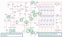
Here you have the new schematic...the same as the old one with some values tweaked...the stand by current is 50 miliamperes to each power transistor, and this is optimized..the total dissipation in stand by mode is 40 watts... very hot...well..you decide if you want all that heat.
Distortion is fine and the ratio from the second to the third harmonic is very good..sensitivity was very reduces and compensation capacitor increased.
Green circled parts are the ones to be modified..trimpot remain mid way but use these power transistors shown..do not try others.... all rigth..the output ones you can change... also the vbe multiplier can be changed but this will result in errors in the base to emitter resistors that you gonna have to be tweaking in a try and error basis till you fix that..so..not a good idea to be searching for troubles.
Be happy... something that was already very good, not it is much more than very good.
Please boys.... do not mess with uncle charlie..i am a hell busy producing the Dx Zim SMPS supply the Kraftwerke..... also making the mini MAKO (400 watts each channel) to go together with that supply..... do your part of the game and let uncle charlie free to work, do not go sending me emails asking more time from your almost dead uncle.
regards,
Carlos
but for sure will work fine.
Here you have the new schematic...the same as the old one with some values tweaked...the stand by current is 50 miliamperes to each power transistor, and this is optimized..the total dissipation in stand by mode is 40 watts... very hot...well..you decide if you want all that heat.
Distortion is fine and the ratio from the second to the third harmonic is very good..sensitivity was very reduces and compensation capacitor increased.
Green circled parts are the ones to be modified..trimpot remain mid way but use these power transistors shown..do not try others.... all rigth..the output ones you can change... also the vbe multiplier can be changed but this will result in errors in the base to emitter resistors that you gonna have to be tweaking in a try and error basis till you fix that..so..not a good idea to be searching for troubles.
Be happy... something that was already very good, not it is much more than very good.
Please boys.... do not mess with uncle charlie..i am a hell busy producing the Dx Zim SMPS supply the Kraftwerke..... also making the mini MAKO (400 watts each channel) to go together with that supply..... do your part of the game and let uncle charlie free to work, do not go sending me emails asking more time from your almost dead uncle.
regards,
Carlos
Attachments
Last edited:
Please, the first one to make it do it one channel only to compare
and please, let me know what you think about... real criticism...with no pain...is it better or not?
I would love to build, or to modify the Blame i have...but is i am soooooo busy!
wiljj78 .... will you make it?.... thank you dear "bahrain"
Invitation to you here:
http://www.youtube.com/watch?v=8VMxj380J98
regards,
Carlos
Last edited:
and please, let me know what you think about... real criticism...with no pain...is it better or not?
I would love to build, or to modify the Blame i have...but is i am soooooo busy!
wiljj78 .... will you make it?.... thank you dear "bahrain"
Invitation to you here:
Invitation to Bahrein - YouTube
regards,
Carlos
Uncle Charlie you really looks like real Bahraini Hahahahaha...

Thank you for the invitation and YES... for sure i will make the new modification and revert back to you.
Thank you sooo much...
Regards,
Willy
Member
Joined 2009
Paid Member
Carlos,
The design in post 1 shows your interesting current source arrangement for the VAS. You have a transistor current source feeding the VAS from the +ve rail and then you have a boostrap pair of resistors between the CCS and the VAS collector.
How does this change the sound compared with plane transistor CCS only, and with bootstrap only ?
I have perceived more punch only
The overall sound looks the same, but the speaker started to move by itself when it was not moving from it's steady point before.
I cannot explain your theoretical things dear Bigun, not only i am not addicted but also i dislike the fact that i know some theories... something i curse on myself is this knowledge.... the ones knows, do not know sonic results...and this means nothing.... say.... have not value as do not help them to make good amplifiers.
In my country we have a say about things we dislike.
- "Eu não sei e tenho raiva de quem sabe" ... but i do think you cannot understand the "range" of that.... this talks about something that is not useless but less usefull.... means "i do not know and i do not want to know or learn"
I do not know and i feel angry about the ones have this knowledge...ahahahahah!... this means the most apocalypt aversion to theories.... i do feel good when i have experiences alike i had in that amplifier.... results obtained while burning my fingers into the workbench.
The ones had the knowledge about theories have bothered me too much when i was young dear Bigun.... circuit assembled from magazine used not to work, some exploded and i had not the knowledge to understand what happened...then i use to write to the designers or to the magazine writers asking for help and they used to snob me because i was "too much young to understand".... alike Hitler that had a strong hate due to things happened in his young days, i do hate these folks till the present days.... they are all dead and i hope they are burning in hell.
Last time answering such kind of questions dear Bigun...this is no good...this just attracts people to bother or they use this as an opportunity to vomit theories here, trying to show they are skilled and good..when i do think they are not one nor other.
You are a very good friend..but next time i will ignore the question.
The good answer...without the combination, or only the CCS, the speaker have not moved from it's stand point...with the combination the speaker moved.... Now you can infer acceleration or amplitude or effect used by the Japanese to test bridges, the balance, the alternation of moves symmetrically perfect.
I am much more inspiration and perspiration than theories dear Bigun... i do discover things while working...say..this results this way or that way...and i do understand the subject related the "kind" of sonics it produces.... you know, it is alike to tune your guitar by ear.... people play and you detect it is out of tune, but you cannot say the string is untuned.... or which particular element is untuned.
I am sorry to say your question will not help you...say...the answer will not help you..... the only help is to tweak and listen and understand the result while listening...it is a sensorial (sensory) thing dear Bigun.
Watching a schematic i can perceive the sound results of sub circuits and values because thousands built... also i can see electrons flow, this appear alike more speed where you have more current and the oposite when you have less current.... this is the kind of "vision" i have developed along these years.... i do use ohms law only and the formula to calculate capacitors... these are usefull things i use everyday.
Speaker move means the enclosure does not stand still in the spatial position you had set before..it moves due to vibrations
regards,
Carlos
Last edited:
The overall sound looks the same, but the speaker started to move by itself when it was not moving from it's steady point before.
Carlos
Carlos what do you mean by this , are you saying the speaker moved because of the offset..?
Member
Joined 2009
Paid Member
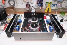
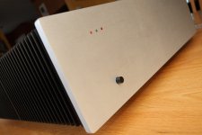
some nice amplifier porn !
Carlos - I am not looking for theories, I am interested in your observations - you have a lot of experience and I think there are a lot of people who don't say much around here but they watch and read what you offer them and they appreciate it.
Anyhow, good to know that you found the dynamics of this VAS loading to be very good compared with the simpler options.
Changed position...was alike "walking away" because of power...you know..you put it 10 inches from back wall and then it is 9 inches
Got it man?
I have some troubles with English...sorry.
Carlos
The speaker moves ... it glides over the ground as a result of strong vibrations caused by power
Carlos
Lol , Ok i get it ...
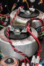
Very pretty... i use this image as advertisement into Brasil.... this way people will be interested to build.
regards,
Carlos
I changed the power cabling routing since then...
Attachments
Member
Joined 2009
Paid Member
Dear Cannonica, i have perceived the best amplifier ever made
related how it looks, related how pretty is resulted....became a little bit messy after you have installed the wires and cables.
I have a suggestion.
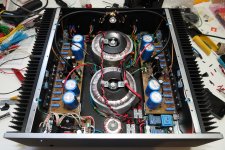
Wires must create a cable (wires together) and make a circular motion inside the enclosure.... touching the enclosure perimeter, and from the cable some wires must exit to be soldered in their spots.
To do that you must codify with colours to identify some specific wire that will need to be soldered in their correct spot.... you must make a provisory, temporary cable alike, so tie down not tigh because you gonna stretch the cable after finish soldering to make your final tie
This is not easy, and waste a lot of wire...and time too.... the idea is to complete a circle with your wire/cable, and then go picking up each colour that gonna exit the main stream (the cable) to be soldered.... they must be attached one to the other and fixed by nylon belts, brackets or tied with some kind of nice rope.
We cannot run AC mains in parallel with audio cables..because this induces hum from the mains frequency...so...mains must run separate in their own cable and having a good distance, clearance, from audio cables and DC supply cables..these two last ones can run together.
To make this stuff pretty you should make all your soldering below the pcboards..keeping the spider alike web out from our vision and inspection.
The moment to do that is when you have your parts alike an exploded view....the image i have posted, the one i like the most..this is the moment to prepare cables.
These are the suggestions..... this produces a lot of hard work, waste a lot of wire because you run the full enclosure perimeter (touching the side panels and goes running placed in between the side panels and the enclosure bottom)... then you pick the wire when it reaches the spot "angle"....this is alike a bus stop..... the street is the cable.... wire goes out from the cable the same way you got out from the bus when you reach your stop point..but all hidden from our eyes...all below pcboards.
You run the full perimeter (as you are not inside a factory) or all wire...and then you may cut one of them that gonna exit from the main cable to be connected almost 5 inches after the point the cable start to run.
If this is confused, i can make it in french and send it to your email....write to uncle charlie and i will forward in french, or other language you want.
I can do in English, German, French, Spanish and Portuguese
nanabrother@hotmail.com
carlos.eugenio1951@yahoo.com
regards,
Carlos
related how it looks, related how pretty is resulted....became a little bit messy after you have installed the wires and cables.
I have a suggestion.
Wires must create a cable (wires together) and make a circular motion inside the enclosure.... touching the enclosure perimeter, and from the cable some wires must exit to be soldered in their spots.
To do that you must codify with colours to identify some specific wire that will need to be soldered in their correct spot.... you must make a provisory, temporary cable alike, so tie down not tigh because you gonna stretch the cable after finish soldering to make your final tie
This is not easy, and waste a lot of wire...and time too.... the idea is to complete a circle with your wire/cable, and then go picking up each colour that gonna exit the main stream (the cable) to be soldered.... they must be attached one to the other and fixed by nylon belts, brackets or tied with some kind of nice rope.
We cannot run AC mains in parallel with audio cables..because this induces hum from the mains frequency...so...mains must run separate in their own cable and having a good distance, clearance, from audio cables and DC supply cables..these two last ones can run together.
To make this stuff pretty you should make all your soldering below the pcboards..keeping the spider alike web out from our vision and inspection.
The moment to do that is when you have your parts alike an exploded view....the image i have posted, the one i like the most..this is the moment to prepare cables.
These are the suggestions..... this produces a lot of hard work, waste a lot of wire because you run the full enclosure perimeter (touching the side panels and goes running placed in between the side panels and the enclosure bottom)... then you pick the wire when it reaches the spot "angle"....this is alike a bus stop..... the street is the cable.... wire goes out from the cable the same way you got out from the bus when you reach your stop point..but all hidden from our eyes...all below pcboards.
You run the full perimeter (as you are not inside a factory) or all wire...and then you may cut one of them that gonna exit from the main cable to be connected almost 5 inches after the point the cable start to run.
If this is confused, i can make it in french and send it to your email....write to uncle charlie and i will forward in french, or other language you want.
I can do in English, German, French, Spanish and Portuguese
nanabrother@hotmail.com
carlos.eugenio1951@yahoo.com
regards,
Carlos
Last edited:
Great explanation Carlos, you don't need to do it in french I'm not sure I want to redo the wiring, as like you said, it's not an easy task, and I don't have any parasitic noise coming from the mains. I had some hum noise before rerouting the mains, but now it's OK.
What I want to do with it now, along enjoying it, is to increase the standby current. But increasing past a certain threshold seems to create instability. I won't modify all the multiple values you suggested recently. I may just try to increase the base-stopping resistor of the drivers from 22R to 56R... And try to increase the bias again.
In any ways, I'm going to post the differences, audible and measured when I'm done.
Regards,
Martin.
I'm not sure I want to redo the wiring, as like you said, it's not an easy task, and I don't have any parasitic noise coming from the mains. I had some hum noise before rerouting the mains, but now it's OK.What I want to do with it now, along enjoying it, is to increase the standby current. But increasing past a certain threshold seems to create instability. I won't modify all the multiple values you suggested recently. I may just try to increase the base-stopping resistor of the drivers from 22R to 56R... And try to increase the bias again.
In any ways, I'm going to post the differences, audible and measured when I'm done.
Regards,
Martin.
This confession (stop resistor increase being a good idea) is rather surprising to me at this time. It makes me question about what would be the optimum value now, hahaha....
Bonfis tried the value of 56R with success, while in every "startup" design of Dr Self, that resistor have a value of 100R.
In the simulator, the higher the value, the more stable the circuit seems. I may start with 56R and try 100R as well. Although I don't have a scope, I expect the high-bias stability to be better with greater value.
Will post results...
You may find that splitting the base stopper values between all the output stages (pre-driver, driver and output device), rather than putting the "whole" stopper on one device may work better.
as an example:- output base stopper ~1r, driver base stopper ~ 22r, pre-driver base stopper ~100r
as an example:- output base stopper ~1r, driver base stopper ~ 22r, pre-driver base stopper ~100r
- Status
- Not open for further replies.
- Home
- Amplifiers
- Solid State
- Dx Blame MKIII-Hx - Builder's thread