Hello again from down south - Tasmania.
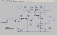
I have a very complicated problem concerning negative feedback for a circuit that I have borrowed from one of the British Universities. I don't have a lot of money to spend on expensive Zetex transistors or special transformers but have two 200va 80V centretapped toroids and a heap of salvaged trannies as shown in the diagram.
I am not a lazy man, - I have tried to understand pol and db and all the rest - but it is wearing me down and without help I will continue to struggle, or, even worse, GIVE UP.
I don't actually need an explanation of how to calculate these values because It has been explained to me before. I just dont have the time to research such a complicated issue, nor the capacity (at this stage) to understand it.
Can someone calculate the values for me?
Values for the components that are highlighted in blue. (think its blue, I'm colour-blind too!)
I am hoping that someone out there with a bit of practical experience (tradesman or engineer perhaps?) might be able to do it 'easier' than I can't do. If that makes sense.
Attachments
Last edited:
neg fb - gain control
Thanks Nigel. That circuit was developed by The university of Sheffield back in 2003. I chose it because it was simple and well explained in the accompanying circuit description. Now I know what a differential amplifier is and where the voltage amplification stage is. My next task is to look up some information (www) on input filter design, I have built a few speaker x'overs, but I use coils & caps, not resistors & caps.
Thanks again. I was on the verge of putting 4 dip switches or a rotary sw. and four resistors in that gap! Is it worth trying 39, 43 & 47 in this manner? A nagging voice is telling me I'm over thinking this problem. Would the circuit below be unnecessary clutter? Not to mention the risk of an accidental open feedback loop - all contacts open.
The following circuit might work;
P.S. I will look up 'PCBCAD' on google and see if I can get a screen shot of the application - it's priced right for a peasant like me!!! The one I use is very easy to use but limited in it's function.
Attachments
Last edited:
I agree with Nigel, it looks pretty good.
Though, I believe 47k is a bit high. The gain of the amp is the ratio of that R to the 1k, so if you use 47k, you get 47 x gain.
Most power amps have around 30 x gain, and a 27k or 33k resistor is better IMHO.
With the 47k you might have to turn your volume control all the way down and that doesn't have a comfortable 'feel'.
My two eurocents worth.
jan didden
Hi there Jan, nice to meet you. It's a very good suggestion. I know very little about this kind of thing, but a little voice told me to put a mini 1P3T-on-on-on switch with 39, 43 & 47 but with Nigel's permission I could make it 27, 30 & 33 then I can try each setting and see how it goes. It really won't take up too much room on the board & I haven't even drawn the pcb yet.
I too like to be able to turn the volume pot up to at-least the 10 o'clock position.
You can take a look at the .gif above if you like, it's pretty boring really but it shows how I would wire the resistors with the pcb switch.
The following may be unnecessary and Idle chit-chat Jan, but I am very excited about getting some oscillation happening.
I scored a giant db meter from a fellow on ebay (200mm Dia.) it is very 'off-road' or 'robust' with a lovely bakelite housing and 150mm pointer. I built a little integrater/amp for the movement and the pointer bounces around really nicely and seems to correspond to the musical peaks or voltage units (switchable) but for me it's just an aesthetic that helps to show how silly I really am! I am going to backlight the dial with a warm LED glow from a circular pcb mounted behind the dial and surrounded with some smd emitters. The whole project will be enclosed in a whoppin great aluminium box - I want lots of room inside there in case this particular design gets warm & I need room for the two transformers 200VA each side. I will put my salvaged yamaha HTR-5840 aluminium heatsink inside the box. it is a really big slab of aluminium with beautifully riveted thin alloy fins. So now you know where I got my output transistors from too!
Once again I would like to thank every one involved for solving my quandry.
Most sincerely, Phil Elliott
Farmer Jack, I note that you use the 2sc4468 and 2sa1695. Do you happen to have SPICE models for them?
Google draws a blank on this. About the best result is a very old thread on this very forum. It only contains one post asking the same question:
http://www.diyaudio.com/forums/parts/81747-2sc4468-2sa1695-spice-models.html
Google draws a blank on this. About the best result is a very old thread on this very forum. It only contains one post asking the same question:
http://www.diyaudio.com/forums/parts/81747-2sc4468-2sa1695-spice-models.html
Input resistor between B and GND and feedback resistor needs to be the same value, otherwise the amp will have big dc offset.
I should have spotted that but I use a resistor in each leg of the LTP.
i.e. one 560r and the other a 1k pot to balance out the LTP and so fix the dc offset.
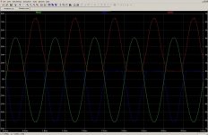
LTspice simulation
I had a go at this circuit with LTspice IV. Spice models for the 2SC4468 and 2SA1695 are not available. The BC612 is another unknown - I can't even google up a datasheet for it. I therefore made a few substitutions. For the BC212 I used the 2SA970 simply because they are already used. For the output I took the tried and trusted 2SA1302 and 2SC3281.
To get the output to swing anywhere near the substantial 55V rails on only 200mV of input, the feedback resistor had to be increased by an order of magnitude. The DC offset is significant at -540mV.
The use of diodes for biasing might have suited the original output devices, but for my substitutes there is not enough control to keep them out of class AB (with all the problems that arises from that). The THD at 1kHz is 0.27% - not bad but not inspiring either.
I will substitute a Vbe multiplier for the diodes and report back. It might also be worth the effort to try a few other complementary pairs.
Attachments
look at JLH 80W mosfet amp to see some ideas on how to optimise the NFB loop and input impedances to result in an amplifier with unfashionably high gain.
BTW,
high gain reduces feedback and that in turn increases the stability margins of the amplifier.
A lower gain amplifier needs more compensation to avoid instability.
BTW,
high gain reduces feedback and that in turn increases the stability margins of the amplifier.
A lower gain amplifier needs more compensation to avoid instability.
amp project
Hi there Tekko, it's a pleasure to meet you.
Guys like me are a big pain in the backside. Ambition and capability don't match!
I really know nothing about this stuff, but I like the pretty colours on the resistors.
I like etching boards, soldering and listening to blues music.
My amp is a first attempt to put something together and learn a bit in the process. I have no dilusions of excellence in this project.
Apparently one of the simulators said the distortion was a bit on the high side.
I have two 200VA 40-0-40 transformers & re-hashed the original circuit in order to use them, BUT when I did the calculations for this amp I was working on the following logic - which may well be, and probably is flawed.
I wanted between 70-100W/Ch (according to the sums I need 40V and 5A peaks).
I figured that even though I used 55VDC rails and selected transistors to suit - that the output would only be swinging up to 40 volts either way.
The transformers (sourced from a matching pair of blown subbies) can only develop 2.5A at 40-0-40 BUT (my logic) said that it's ok because I'm only using about 28-0-28 and therefore I can somehow suck more amps out of it: 200va/56=3.6A THIS IS WRONG i CAN SEE HOW STUPID IT REALLY IS WHEN i TYPE IT OUT LIKE THIS. THAT PIECE OF WIRE IN THE SECONDARY WINDING WILL ONLY CARRY A CERTAIN AMPERAGE AND THAT'S - 2.5A
The negative feedback loop had me puzzled but now I have decided to look at this circuit in the same way that I look at an op-amp and can now see that the ratio of the two resistors form a ratio that is; the 'gain' figure.
Thankyou for your comments and suggestions and rest assured that I just wont give up!
Cheers and bye for now.
dodgey amp
Yes, I was wondering about a few of those caps, especially the one in paralell with the bias arrangement that sustains that voltage over low frequencies - I was going to poke one of my crossover caps in there.
Phil
but too much gain and ur back in oscillatorville again.
All my amps so far uses 39k and 1-1.2k for the feedback network along with a 100µF bipolar/nonpolar capacitor.
Yes, I was wondering about a few of those caps, especially the one in paralell with the bias arrangement that sustains that voltage over low frequencies - I was going to poke one of my crossover caps in there.
Phil
U can take a look at my amp stuffz in this link: experimentonomen's Photo Albums - Imgur
regarding the circuit
OK, see if I got it right.
The series resistor in the feedback line needs to be 33k?
The 27k ground reference in the input filters needs to match this, and therefore is 33k too?
NEXT Question; Can I improve the THD by REDUCING the gain, OR any other means?
NOTE; it is not imperative for me to get a huge amount of power out of this amp, even if I could get 70 clean watts I'd be happy.
PS: I don't mind re-hashing the circuit, so if you are good at sketching you might jot down a few ideas. It needs to be in laymans terms though as my electronics knowledge is limited.
PPS: Do you think I should buy a pair of those Chinese cloned boards, and just use my transformers to power them? Kit form.
I'd stay away from chinese clones.
Yes the resistor between input and ground needs to match the feedback resistor.
I'm working on a design that will output 300-500W into 4 ohms at 50-60V rails, but its pretty similar to the DX blame series so im prolly wasting my time on it.
Yes the resistor between input and ground needs to match the feedback resistor.
I'm working on a design that will output 300-500W into 4 ohms at 50-60V rails, but its pretty similar to the DX blame series so im prolly wasting my time on it.
Alright, I have two options at this stage; firstly I can stick with this design and waste every one's time - probably not a good idea. Secondly I could loosen my purse strings and buy a few new components but use the transformers.
Can someone point me in the right direction to find a circuit with 55VDC rails. Class A or AB (dont mind).
Cheers
Can someone point me in the right direction to find a circuit with 55VDC rails. Class A or AB (dont mind).
Cheers
- Status
- This old topic is closed. If you want to reopen this topic, contact a moderator using the "Report Post" button.
- Home
- Amplifiers
- Solid State
- Engineer, help please - Neg. feedback/infilters